SECTION 5 - ADJUSTMENTS
5.1 STEERING/BRAKES
If machine is not as responsive as desired when either Traction Lever is squeezed, one or both brakes should be adjusted as follows:
1.Operate mower on level terrain with Transmission Shift Lever in No. 1 position. Determine which brake requires adjustment.
2.Stop engine, remove the key from switch and disconnect spark plug wire from spark plug. Secure wire away from plug.
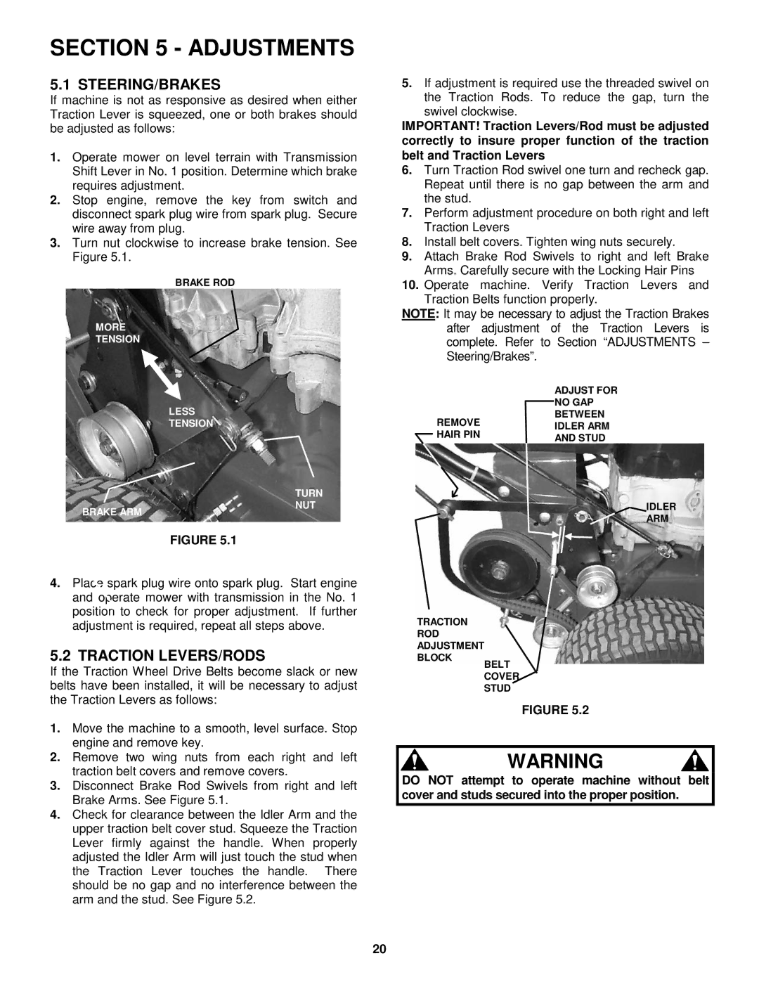
3.Turn nut clockwise to increase brake tension. See Figure 5.1.
BRAKE ROD
MORE
TENSION
LESS
TENSION
5.If adjustment is required use the threaded swivel on the Traction Rods. To reduce the gap, turn the swivel clockwise.
IMPORTANT! Traction Levers/Rod must be adjusted correctly to insure proper function of the traction belt and Traction Levers
6.Turn Traction Rod swivel one turn and recheck gap. Repeat until there is no gap between the arm and the stud.
7.Perform adjustment procedure on both right and left Traction Levers
8.Install belt covers. Tighten wing nuts securely.
9.Attach Brake Rod Swivels to right and left Brake Arms. Carefully secure with the Locking Hair Pins
10.Operate machine. Verify Traction Levers and Traction Belts function properly.
NOTE: It may be necessary to adjust the Traction Brakes after adjustment of the Traction Levers is complete. Refer to Section “ADJUSTMENTS – Steering/Brakes”.
| ADJUST FOR | |
| NO GAP | |
REMOVE | BETWEEN | |
IDLER ARM | ||
HAIR PIN | ||
AND STUD | ||
|
BRAKE ARM
TURN
NUT
IDLER
ARM
FIGURE 5.1
4.spark plug wire onto spark plug. Start engine
and | mower with transmission in the No. 1 |
| to check for proper adjustment. If further |
adjustment is required, repeat all steps above.
5.2 TRACTION LEVERS/RODS
If the Traction Wheel Drive Belts become slack or new belts have been installed, it will be necessary to adjust the Traction Levers as follows:
1.Move the machine to a smooth, level surface. Stop engine and remove key.
2.Remove two wing nuts from each right and left traction belt covers and remove covers.
3.Disconnect Brake Rod Swivels from right and left Brake Arms. See Figure 5.1.
4.Check for clearance between the Idler Arm and the upper traction belt cover stud. Squeeze the Traction Lever firmly against the handle. When properly adjusted the Idler Arm will just touch the stud when the Traction Lever touches the handle. There should be no gap and no interference between the arm and the stud. See Figure 5.2.
TRACTION
ROD
ADJUSTMENT
BLOCK
BELT
COVER
STUD
FIGURE 5.2
WARNING
DO NOT attempt to operate machine without belt cover and studs secured into the proper position.
20