SECTION 5 - ADJUSTMENTS
5.3 HANDLE HEIGHT
The operator handle can be adjusted for operator comfort as follows:
1.Loosen the upper carriage bolt and nut on both left and right lower handles. See Figure 5.3.
2.Remove lower carriage bolt and nut from both left and right handles.
3.Raise or lower handlebar to desired height. See Figure 5.3.
4.Align handle with one of the adjustment holes in the tank support bracket and insert the carriage bolt. See Figure 5.3.
5.Verify that the handle is still at desired height. Using nuts removed in Step 2, tighten both lower carriage bolts securely.
6.Securely tighten both upper carriage bolts and nuts.
7.The Traction Levers will require adjustment after the handle height has been adjusted. Refer to Section “ADJUSTMENTS – Traction Levers/Rods”.
8.The Transmission Shift Lever linkage will require adjustment after the handle height has been adjusted. Refer to Section “ADJUSTMENTS – Transmission Shift Lever”.
RAISE
LOOSEN
UPPER
CARRIAGE
BOLT
LOWER
REMOVE
LOWER
CARRIAGE
BOLT
FIGURE 5.3
5.4TRANSMISSION SHIFT LEVER ADJUSTMENT
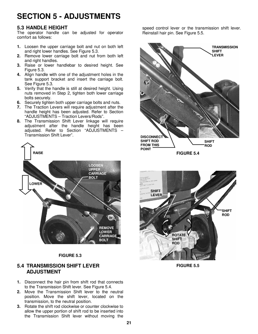
1.Disconnect the hair pin from shift rod that connects to the Transmission Shift lever. See Figure 5.4.
2.Move the Transmission Shift lever to the neutral position. Move the shift lever, located on the transmission, to the neutral position.
3.Rotate the shift rod clockwise or counter clockwise to allow the upper portion of shift rod to be inserted into the Transmission Shift lever without moving the
speed control lever or the transmission shift lever. Reinstall hair pin. See Figure 5.5.
TRANSMISSION
SHIFT
LEVER
DISCONNECT |
|
SHIFT ROD | SHIFT |
FROM THIS | ROD |
POINT |
|
FIGURE 5.4
SHIFT
LEVER
SHIFT
ROD
ROTATE
SHIFT
ROD
FIGURE 5.5
21