SNAPPER 21" STEEL DECK COMMERCIAL WALK BEHIND MOWERS
INTRODUCTION: The SNAPPER Walk Behind Mowers are shipped almost fully assembled and require minimal
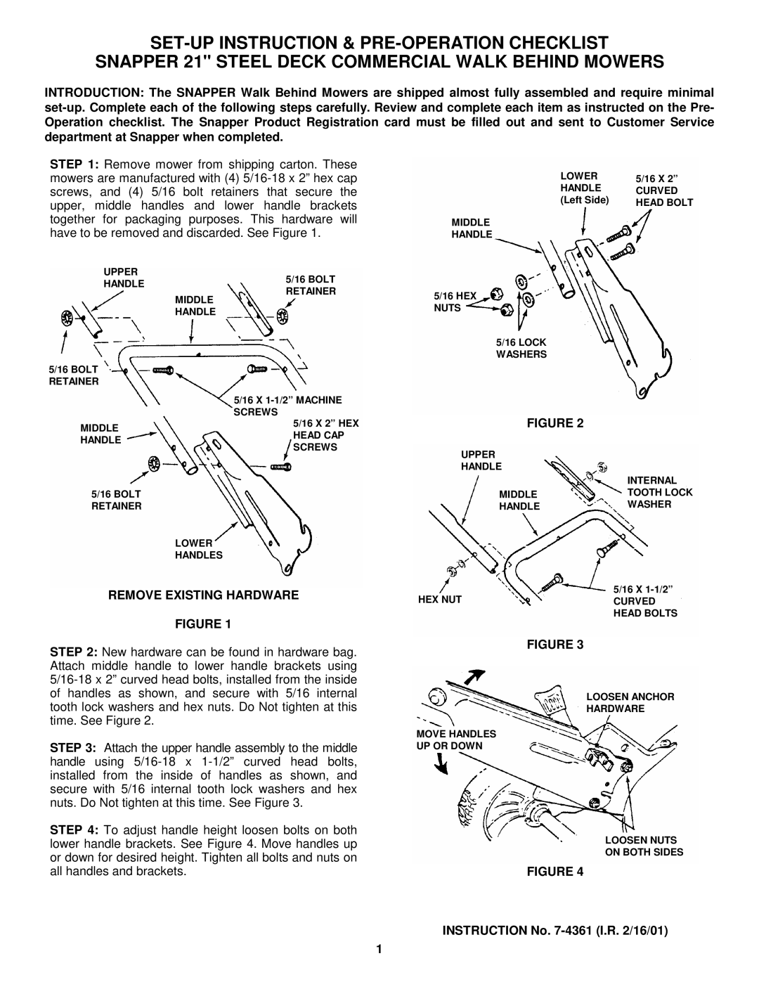
STEP 1: Remove mower from shipping carton. These mowers are manufactured with (4)
UPPER
HANDLE | 5/16 BOLT | |
RETAINER | ||
| ||
| MIDDLE | |
| HANDLE | |
5/16 BOLT |
| |
RETAINER |
| |
| 5/16 X | |
| SCREWS | |
MIDDLE | 5/16 X 2” HEX | |
HEAD CAP | ||
HANDLE | ||
SCREWS | ||
| ||
5/16 BOLT |
| |
RETAINER |
| |
| LOWER | |
| HANDLES |
REMOVE EXISTING HARDWARE
FIGURE 1
STEP 2: New hardware can be found in hardware bag. Attach middle handle to lower handle brackets using
STEP 3: Attach the upper handle assembly to the middle handle using
STEP 4: To adjust handle height loosen bolts on both lower handle brackets. See Figure 4. Move handles up or down for desired height. Tighten all bolts and nuts on all handles and brackets.
LOWER | 5/16 X 2” |
HANDLE | CURVED |
(Left Side) | HEAD BOLT |
MIDDLE
HANDLE
5/16 HEX NUTS
5/16 LOCK WASHERS
FIGURE 2
UPPER |
|
HANDLE |
|
| INTERNAL |
MIDDLE | TOOTH LOCK |
HANDLE | WASHER |
5/16 X
HEX NUTCURVED HEAD BOLTS
FIGURE 3
LOOSEN ANCHOR
HARDWARE
MOVE HANDLES
UP OR DOWN
LOOSEN NUTS
ON BOTH SIDES
FIGURE 4
INSTRUCTION No. 7-4361 (I.R. 2/16/01)
1