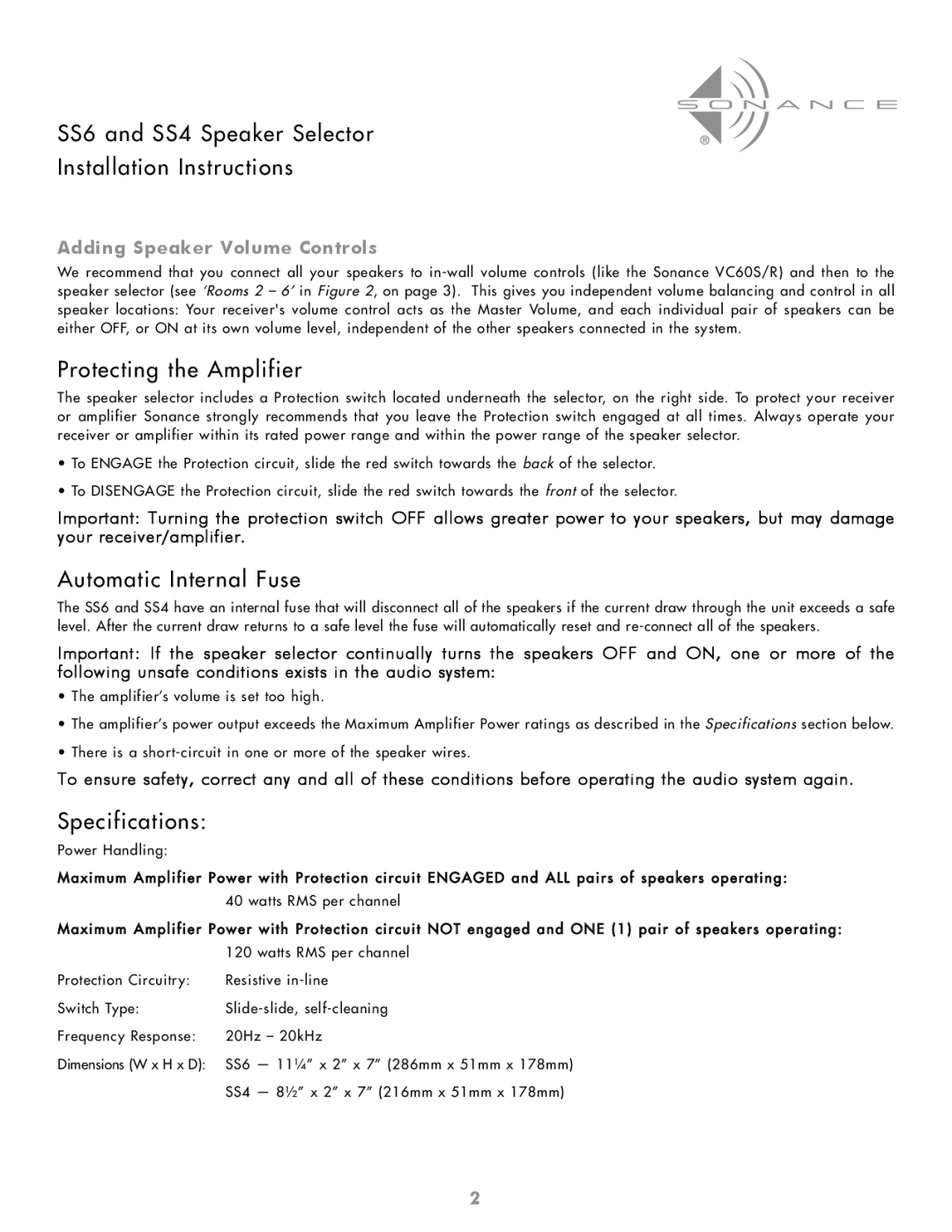
SS6 specifications
The Sonance SS6 represents a remarkable fusion of cutting-edge technology and elegant design, catering to the needs of audiophiles and casual listeners alike. Engineered primarily for in-ceiling or in-wall installation, the SS6 speaker system is built to provide high-quality audio performance that blends seamlessly into any environment.One of the standout features of the Sonance SS6 is its advanced speaker architecture. It incorporates a 6.5-inch polypropylene cone woofer designed to deliver rich and balanced sound across a wide frequency range. This woofer is specifically crafted to reproduce deep bass notes while maintaining clarity in mids and highs. Complementing the woofer is a 1-inch pivoting aluminum dome tweeter that ensures accurate high-frequency response. This pivoting capability allows users to direct sound towards specific listening areas, enhancing the overall audio experience.
The SS6 also utilizes Sonance's proprietary technologies, including the Patented “Vented” design, which helps to minimize distortion and improve overall sound quality. This design feature ensures that the speakers perform exceptionally well, providing clear sound even at higher volumes. In addition, the speakers are equipped with moisture-resistant materials, making them suitable for installation in environments prone to humidity, such as bathrooms and patios.
Aesthetically, the Sonance SS6 excels with its low-profile design. The speaker grille can be painted to match the ceiling or wall, allowing for a custom look that blends in with any décor. This is particularly beneficial in home theaters and living spaces where visual appeal is just as important as audio performance.
Installation is made easier with the SS6’s built-in dog legs and easy-to-use mounting brackets, which provide a secure fit in a variety of wall and ceiling depths. This allows both professional installers and DIY enthusiasts to achieve optimal placement with minimal effort.
In terms of versatility, the Sonance SS6 is compatible with a variety of audio systems and can be used in stereo or surround sound setups. Its ability to work seamlessly with both home theater systems and multi-room audio setups enhances its appeal for users who appreciate a comprehensive audio experience.
In summary, the Sonance SS6 combines innovative technology, aesthetic integration, and versatile performance in a compact design, making it a premier choice for anyone seeking superior in-ceiling or in-wall audio solutions. Whether for a cinematic experience or subtle background music, the SS6 is engineered to meet diverse audio demands while effortlessly enhancing the ambiance of any space.

