December 28, 2005


Revision 2.8

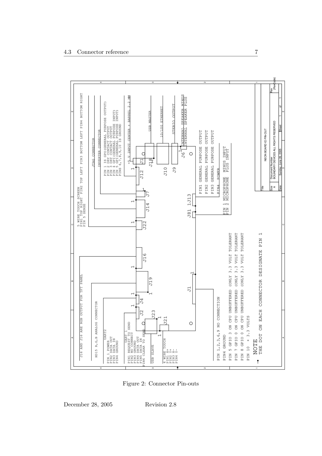
Figure 2: Connector


Pin-outs


A


B


C


D


E


5 WIRE TOUCH SCREEN


J16 AND J16 ARE RGB OUTPUT FOR TFT PANEL


PIN1 TOP RIGHT


PIN2 TOP LEFT

PIN3 BOTTOM LEFT PIN4 BOTTOM RIGHT


PIN 5 SENSE


JTAG CONNECTOR


HD15 R,G,B ANALOG CONNECTOR


INVERTER CONNECTOR


4


4


PIN 1 IS GPO(GENERAL PURPOSE OUTPUT)


UART2


PIN 1 POWER


PIN 2 DRY CONTACT OUTPUT


PIN2 DATA OUT


PIN 3 DRY CONTACT OUTPUT


PIN3 DATA IN


PIN 4 GPI(GENERAL PURPOSE INPUT)


PIN4 GROUND


PIN 5 GPI(GENERAL PURPOSE INPUT)


PINS 6,7,8,9,10 IS GROUND


UART 1


PIN1 REQUEST TO SEND

1

1

1

1


1

+5 V INPUT CENTER + BARREL 2.2 MM


PIN2 NO CONNECT

1


PIN3 GROUND


PIN4 DATA OUT


PIN5 DATA IN

J2

J4

J16

J22


1

J12

J1


PIN6 CLEAR TO SEND


J14


1

J19


J7

J18

USB MASTER


J23


3

USB SLAVE


1

3


1

1


10/100 ETHERNET


4 WIRE TOUCH

J21


J10


PIN1 X+


PIN2 Y+


STERIO OUTPUT


PIN3 X-


J9


PIN4 Y-


J1


J81

1J13


J61


INTERNAL SPEAKER MINUS


INTERNAL SPEAKER PLUS


1


PIN1 GENERAL PURPOSE OUTPUT


2


PIN2 GENERAL PURPOSE OUTPUT


2


PIN3 GENERAL PURPOSE OUTPUT


PIN 1,2,3,6,9 NO CONNECTION


PIN4

POWER


PIN4 GROUND


PIN 1 MICROPHONE

MINUS INPUT


PIN 5 GPIO 3 ON CPU UNBUFFERED (ONLY 3.3 VOLT TOLERANT


PIN 2 MICROPHONE

PLUS INPUT


PIN 7 GPIO 0 ON CPU UNBUFFERED (ONLY 3.3 VOLT TOLERANT


PIN 8 GPIO 0 ON CPU UNBUFFERED (ONLY 3.3 VOLT TOLERANT


PIN 10 + 3.3 VOLTS


NOTE


1


1


THE DOT ON EACH CONNECTOR DESIGNATE PIN 1


Title


NEON BOARD IO PIN-OUT


Size

Document Number


Rev


A

BOUNDARY DEVICES ALL RIGHTS RESERVED


{RevCode}


Date:


Sunday, June 26, 2005


Sheet

1

of 1


A


B


C


D


E


4.3 Connector reference

7

Page 7
Image 7
Sonic Alert 2.8 user manual Connector

2.8 specifications

Sonic Alert 2.8 is a state-of-the-art alarm clock designed primarily for individuals with hearing impairments or those who simply require a more robust waking mechanism. Engineered to deliver high-performance features and proprietary technologies, this device stands out as a reliable solution for a restful night and an efficient morning wake-up.

One of the hallmark features of Sonic Alert 2.8 is its powerful bed shaker. This vibration mechanism is designed to be placed under your pillow or mattress, providing a tactile wake-up signal. For individuals who may not respond to traditional auditory alarms, this function ensures that they start their day without being late for appointments or commitments.

The alarm clock also boasts an impressive sound output. With adjustable volume settings, users can customize the alarm sound to their preference, ranging from gentle melodies to loud, attention-grabbing beeps. This flexibility caters to diverse user needs, allowing for a more personalized waking experience.

In terms of visibility, Sonic Alert 2.8 integrates a bright, flashing strobe light that works in conjunction with the auditory alarms. This visual cue appeals to those who may have difficulty hearing and can be beneficial in noisy environments. The strobe light can be set to flash in a specific pattern or color, adding another layer of customization to the waking experience.

Moreover, Sonic Alert 2.8 is engineered with a user-friendly interface, featuring large, easy-to-read display numbers that are perfect for the visually impaired. The intuitive buttons allow for straightforward operation, including setting alarms or toggling through various functions with minimal hassle.

The device is also equipped with a battery backup feature, ensuring that alarms will still sound even during power outages. This functionality provides peace of mind, knowing that important morning engagements won't be missed.

Additionally, Sonic Alert 2.8 is constructed with durable materials, making it a reliable companion for years to come. The sleek design and compact size make it easy to place on any bedside table without taking up excessive space.

Overall, Sonic Alert 2.8 exemplifies innovation in alarm technology, combining advanced features and thoughtful design to cater to users' unique needs. Whether for the hard of hearing or anyone who simply desires a more effective wake-up method, this alarm clock is an ideal choice.