Ver 1.1 2001.07
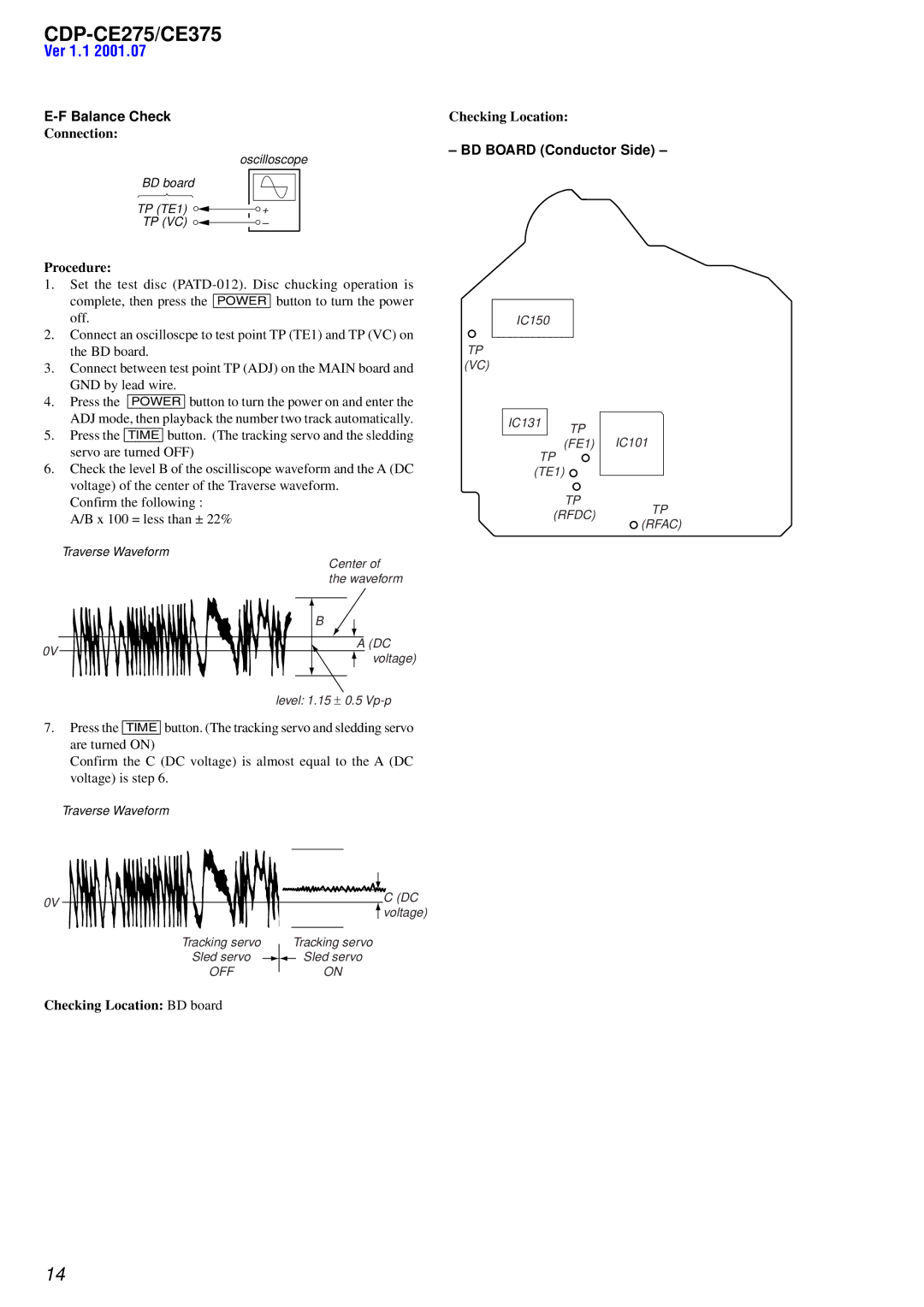
| Checking Location: |
Connection: |
|
| – BD BOARD (Conductor Side) – |
| oscilloscope |
BD board |
|
TP (TE1) | + |
TP (VC) | – |
Procedure:
1.Set the test disc
2.Connect an oscilloscpe to test point TP (TE1) and TP (VC) on the BD board.
3.Connect between test point TP (ADJ) on the MAIN board and GND by lead wire.
4.Press the [POWER] button to turn the power on and enter the ADJ mode, then playback the number two track automatically.
5.Press the [TIME] button. (The tracking servo and the sledding servo are turned OFF)
6.Check the level B of the oscilliscope waveform and the A (DC voltage) of the center of the Traverse waveform.
Confirm the following : A/B x 100 = less than ± 22%
Traverse Waveform
Center of the waveform
B
A (DC
0V
voltage)
level: 1.15 ± 0.5
7.Press the [TIME] button. (The tracking servo and sledding servo are turned ON)
Confirm the C (DC voltage) is almost equal to the A (DC voltage) is step 6.
Traverse Waveform
IC150
TP (VC)
IC131 | TP |
| |
| (FE1) IC101 |
TP (TE1)
TP
(RFDC) TP (RFAC)
0V |
|
|
|
|
|
|
|
|
|
| C (DC |
|
|
|
|
|
|
|
|
|
| voltage) | |
|
|
|
|
|
|
|
|
|
|
| |
|
|
|
|
|
|
|
|
|
|
|
|
| Tracking servo |
|
|
| Tracking servo | ||||||
|
| ||||||||||
| Sled servo |
|
|
|
|
|
| Sled servo | |||
|
|
|
|
|
| ||||||
| OFF |
|
|
|
| ON | |||||
|
| ||||||||||
Checking Location: BD board
14