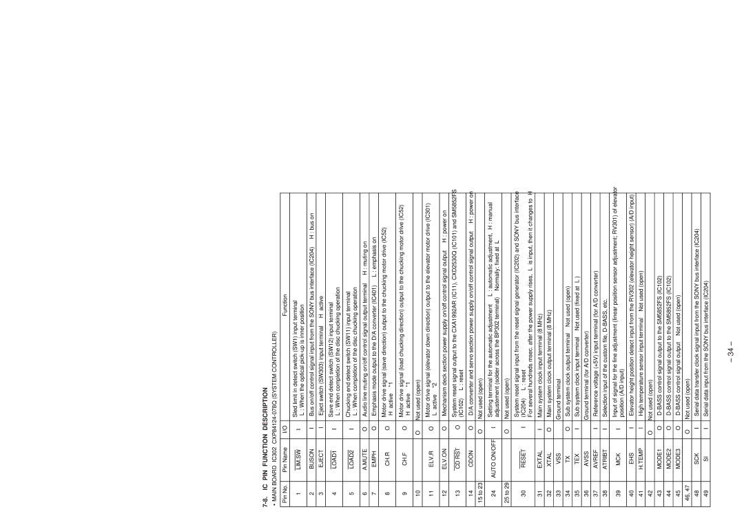
7-8. IC PIN FUNCTION DESCRIPTION
•MAIN BOARD IC302 CXP84124-078Q (SYSTEM CONTROLLER)
Pin No. |
| Pin Name | I/O |
|
|
|
| Function |
| ||
|
|
|
|
|
|
| |||||
1 |
| LIM.SW | I | Sled limit in detect switch (SW1) input terminal |
| ||||||
| “L”: When the optical |
|
| ||||||||
|
|
|
|
|
|
| |||||
|
|
|
|
|
| ||||||
2 |
| BUSON | I | Bus on/off control signal input from the SONY bus interface (IC204) | “H”: bus on | ||||||
|
|
|
|
|
|
| |||||
3 |
| EJECT | I | Eject switch (SW303) input terminal | “H” active |
| |||||
|
|
|
|
|
|
|
| ||||
4 |
| LOAD1 | I | Save end detect switch (SW12) input terminal |
|
| |||||
| “L”: When completion of the disc chucking operation |
| |||||||||
|
|
|
|
|
| ||||||
|
|
|
|
|
|
| |||||
5 |
| LOAD2 | I | Chucking end detect switch (SW11) input terminal |
| ||||||
| “L”: When completion of the disc chucking operation |
| |||||||||
|
|
|
|
|
| ||||||
|
|
|
|
| |||||||
6 |
| A.MUTE | O | Audio line muting on/off control signal output terminal “H”: muting on | |||||||
|
|
|
|
| |||||||
7 |
| EMPH | O | Emphasis mode output to the D/A converter (IC401) “L”: emphasis on | |||||||
|
|
|
|
|
| ||||||
8 |
| CH.R | O | Motor drive signal (save direction) output to the chucking motor drive (IC52) | |||||||
| “H” active | *1 |
|
|
|
| |||||
|
|
|
|
|
|
|
|
| |||
|
|
|
|
|
| ||||||
9 |
| CH.F | O | Motor drive signal (load chucking direction) output to the chucking motor drive (IC52) | |||||||
| “H” active | *1 |
|
|
|
| |||||
|
|
|
|
|
|
|
|
| |||
|
|
|
|
|
|
|
|
|
| ||
10 |
|
| — | O | Not used (open) |
|
|
|
| ||
|
|
|
|
|
| ||||||
11 |
| ELV.R | O | Motor drive signal (elevator down direction) output to the elevator motor drive (IC301) | |||||||
| “L” active |
| *2 |
|
|
|
| ||||
|
|
|
|
|
|
|
|
|
| ||
|
|
|
|
|
| ||||||
12 |
| ELV.ON | O | Mechanism deck section power supply on/off control signal output | “H”: power on | ||||||
|
|
|
|
|
| ||||||
13 |
| CD RST | O | System reset signal output to the CXA1992AR (IC11), CXD2530Q (IC101) and SM5852FS | |||||||
| (IC102) | “L”: reset |
|
|
|
| |||||
|
|
|
|
|
|
|
|
| |||
|
|
|
|
|
| ||||||
14 |
| CDON | O | D/A converter and servo section power supply on/off control signal output “H”: power on | |||||||
|
|
|
|
|
|
|
|
|
| ||
15 to 23 |
|
| — | O | Not used (open) |
|
|
|
| ||
|
|
|
|
|
|
| |||||
24 |
| AUTO ON/OFF | I | Setting terminal for the automatic adjustment | “L”: automatic adjustment, “H”: manual | ||||||
| adjustement (solder across the BP302 terminal) | Normally: fixed at “L” | |||||||||
|
|
|
|
| |||||||
|
|
|
|
|
|
|
|
|
| ||
25 to 29 |
|
| — | O | Not used (open) |
|
|
|
| ||
|
|
|
|
|
| ||||||
|
|
|
|
| System reset signal input from the reset signal generator (IC202) and SONY bus interface | ||||||
30 |
| RESET | I | (IC204) | “L”: reset |
|
|
|
| ||
|
|
|
|
| For several hundreds msec. after the power supply rises, “L” is input, then it changes to “H” | ||||||
|
|
|
|
|
|
| |||||
31 |
| EXTAL | I | Main system clock input terminal (8 MHz) |
|
| |||||
|
|
|
|
|
|
| |||||
32 |
| XTAL | O | Main system clock output terminal (8 MHz) |
|
| |||||
|
|
|
|
|
|
|
|
| |||
33 |
| VSS | — | Ground terminal |
|
|
|
| |||
|
|
|
|
|
|
|
| ||||
34 |
|
| TX | O | Sub system clock output terminal | Not used (open) |
| ||||
|
|
|
|
|
|
| |||||
35 |
| TEX | I | Sub system clock input terminal | Not used (fixed at “L”) |
| |||||
|
|
|
|
|
|
|
| ||||
36 |
| AVSS | — | Ground terminal (for A/D converter) |
|
|
| ||||
|
|
|
|
|
| ||||||
37 |
| AVREF | I | Reference voltage (+5V) input terminal (for A/D converter) |
| ||||||
|
|
|
|
|
| ||||||
38 |
| ATRIBT | I | Selection input of the custom file, |
| ||||||
|
|
|
|
|
| ||||||
39 |
| MCK | I | Input of signal for the fine adjustment (linear position sensor adjustment; RV301) of elevator | |||||||
| position (A/D input) |
|
|
|
| ||||||
|
|
|
|
|
|
|
|
| |||
|
|
|
|
| |||||||
40 |
| EHS | I | Elevator height position detect input from the RV302 (elevator height sensor) (A/D input) | |||||||
|
|
|
|
|
|
| |||||
41 |
| H.TEMP | I | High temperature sensor input terminal | Not used (open) |
| |||||
|
|
|
|
|
|
|
|
|
| ||
42 |
|
| — | O | Not used (open) |
|
|
|
| ||
|
|
|
|
|
| ||||||
43 |
| MODE1 | O |
| |||||||
|
|
|
|
|
| ||||||
44 |
| MODE2 | O |
| |||||||
|
|
|
|
|
| ||||||
45 |
| MODE3 | O |
| |||||||
|
|
|
|
|
|
|
|
|
| ||
46, 47 |
|
| — | O | Not used (open) |
|
|
|
| ||
|
|
|
|
| |||||||
48 |
| SCK | I | Serial data transfer clock signal input from the SONY bus interface (IC204) | |||||||
|
|
|
|
|
|
| |||||
49 |
|
| SI | I | Serial data input from the SONY bus interface (IC204) |
| |||||
|
|
|
|
|
|
|
|
|
|
|
|
– 34 –