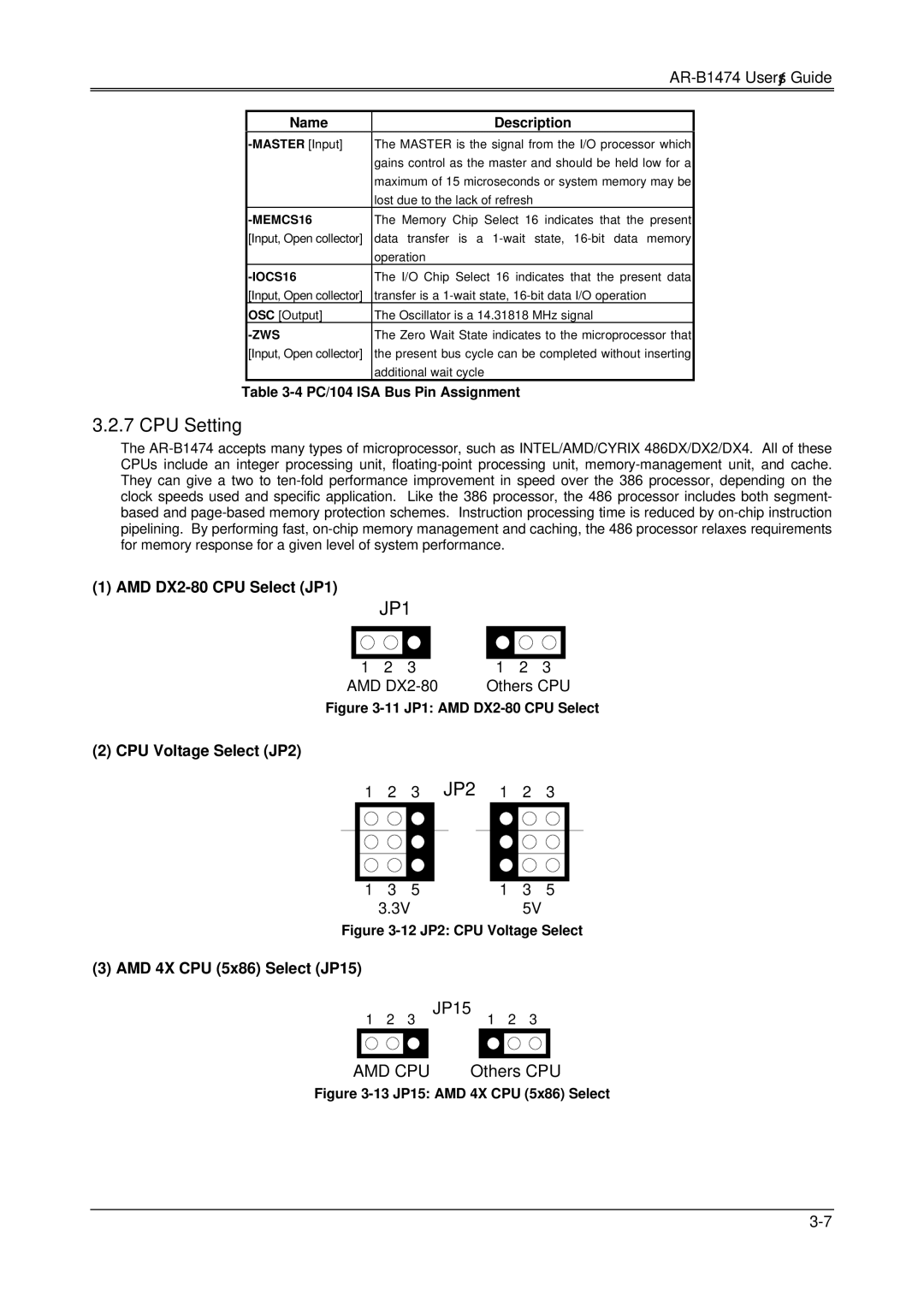
DX4, AR-B1474, 486DX specifications
The Sony 486DX, AR-B1474, and DX4 are notable examples of advanced computing technologies from the early to mid-1990s, a time when personal computers were rapidly evolving to meet increasing user demands. These systems played a pivotal role in shaping the landscape of modern computing.The Sony 486DX is built around the popular Intel 80486 microprocessor, which was a significant step up from its predecessor, the 386. The 486DX featured a 32-bit architecture and introduced integrated cache memory, which greatly enhanced data processing speeds and overall system performance. Operating at clock speeds typically ranging from 25 to 100 MHz, the 486DX models provided a solid foundation for running more sophisticated software applications and advanced games of the era.
Accompanying the 486DX was the AR-B1474 motherboard, designed to maximize the potential of the 486 architecture. This motherboard featured support for up to 512 KB of level 2 cache memory, further boosting performance for data-heavy tasks. The AR-B1474 also included extensive connectivity options, with ISA slots for legacy devices, as well as support for EISA, making it compatible with a wide range of hardware peripherals. This versatility made the AR-B1474 a popular choice among builders of custom desktop PCs during its time.
The DX4, another significant milestone, built upon the 486 architecture by introducing a clock-doubling technique. By effectively allowing the processor to perform operations at up to three times its base clock speed (typically 75 or 100 MHz), the DX4 could handle even more demanding applications, thereby providing users with significant performance improvements without requiring a complete overhaul of their systems.
Both the 486DX and DX4 processors facilitated advancements in multimedia capabilities, with improved graphics rendering and audio performance that supported CD-ROMs and early gaming technologies. This made them particularly appealing to consumers looking for a versatile machine for both work and entertainment.
Overall, the combination of the Sony 486DX, AR-B1474 motherboard, and DX4 processor exemplifies a significant chapter in computing history, showcasing how hardware advancements seamlessly integrated with user needs for performance and flexibility. As these technologies laid the groundwork for future innovations, they remain noteworthy for their contributions to the evolution of personal computing.

