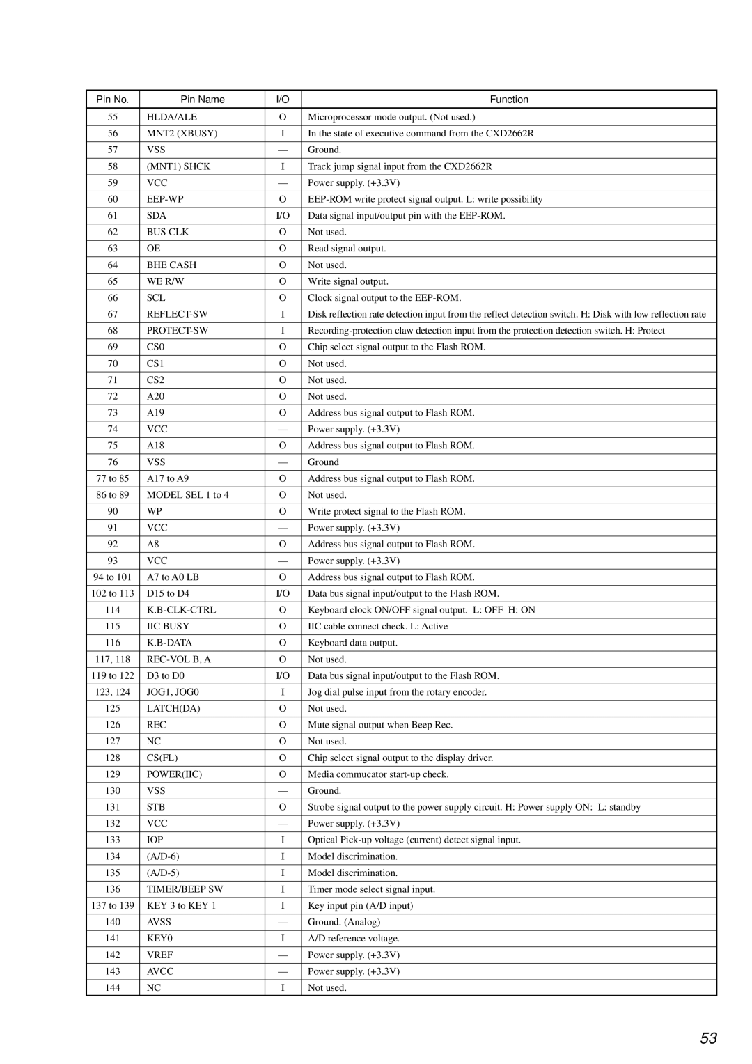
Pin No.

Pin Name

I/O

Function


55

HLDA/ALE

O

Microprocessor mode output. (Not used.)


56

MNT2 (XBUSY)

I

In the state of executive command from the CXD2662R


57

VSS

Ground.


58

(MNT1) SHCK

I

Track jump signal input from the CXD2662R


59

VCC

Power supply. (+3.3V)


60

EEP-WP

O

EEP-ROM write protect signal output. L: write possibility


61

SDA

I/O

Data signal input/output pin with the EEP-ROM.


62

BUS CLK

O

Not used.


63

OE

O

Read signal output.


64

BHE CASH

O

Not used.


65

WE R/W

O

Write signal output.


66

SCL

O

Clock signal output to the EEP-ROM.


67

REFLECT-SW

I

Disk reflection rate detection input from the reflect detection switch. H: Disk with low reflection rate


68

PROTECT-SW

I

Recording-protection claw detection input from the protection detection switch. H: Protect


69

CS0

O

Chip select signal output to the Flash ROM.


70

CS1

O

Not used.


71

CS2

O

Not used.


72

A20

O

Not used.


73

A19

O

Address bus signal output to Flash ROM.


74

VCC

Power supply. (+3.3V)


75

A18

O

Address bus signal output to Flash ROM.


76

VSS

Ground


77 to 85

A17 to A9

O

Address bus signal output to Flash ROM.


86 to 89

MODEL SEL 1 to 4

O

Not used.


90

WP

O

Write protect signal to the Flash ROM.


91

VCC

Power supply. (+3.3V)


92

A8

O

Address bus signal output to Flash ROM.


93

VCC

Power supply. (+3.3V)


94 to 101

A7 to A0 LB

O

Address bus signal output to Flash ROM.


102 to 113

D15 to D4

I/O

Data bus signal input/output to the Flash ROM.


114

K.B-CLK-CTRL

O

Keyboard clock ON/OFF signal output. L: OFF H: ON


115

IIC BUSY

O

IIC cable connect check. L: Active


116

K.B-DATA

O

Keyboard data output.


117, 118

REC-VOL B, A

O

Not used.


119 to 122

D3 to D0

I/O

Data bus signal input/output to the Flash ROM.


123, 124

JOG1, JOG0

I

Jog dial pulse input from the rotary encoder.


125

LATCH(DA)

O

Not used.


126

REC

O

Mute signal output when Beep Rec.


127

NC

O

Not used.


128

CS(FL)

O

Chip select signal output to the display driver.


129

POWER(IIC)

O

Media commucator start-up check.


130

VSS

Ground.


131

STB

O

Strobe signal output to the power supply circuit. H: Power supply ON: L: standby


132

VCC

Power supply. (+3.3V)


133

IOP

I

Optical Pick-up voltage (current) detect signal input.


134

(A/D-6)

I

Model discrimination.


135

(A/D-5)

I

Model discrimination.


136

TIMER/BEEP SW

I

Timer mode select signal input.


137 to 139

KEY 3 to KEY 1

I

Key input pin (A/D input)


140

AVSS

Ground. (Analog)


141

KEY0

I

A/D reference voltage.


142

VREF

Power supply. (+3.3V)


143

AVCC

Power supply. (+3.3V)


144

NC

I

Not used.


53

Page 53
Image 53
Sony KMS-2608/J1N, MDM-7A, NEW specifications Hlda/Ale

KMS-2608/J1N, MDM-7A, NEW specifications

Sony has long been a leader in the realm of electronic innovation, and the introduction of the NEW MDM-7A and KMS-2608/J1N models further solidifies this position. These devices are a testament to Sony's commitment to delivering cutting-edge technology that enhances user experience across various applications.

The MDM-7A, a multi-channel digital mixer, offers advanced audio processing capabilities, ideal for both studio and live sound environments. One of its standout features is its high-resolution 24-bit audio processing, which ensures crystal-clear sound reproduction and fidelity. The MDM-7A supports a wide range of audio formats, making it compatible with various production environments. Moreover, its intuitive user interface facilitates easy navigation and control over numerous audio channels while maintaining flexibility for complex setups.

On the other hand, the KMS-2608/J1N is a multichannel audio management system designed for more extensive sound setups. One of its primary features is the smart signal routing capability, which allows users to manage audio signals efficiently across different outputs. This is especially beneficial in large-scale events or installations where sound management can become challenging. With support for both analog and digital audio inputs, the KMS-2608/J1N caters to a variety of equipment, ensuring seamless integration with existing systems.

In terms of connectivity, both devices are equipped with multiple input and output options, including XLR and TRS connectors, along with digital interfaces such as AES/EBU and S/PDIF. This flexibility allows users to customize their audio setups according to specific needs and preferences.

Another defining characteristic of the MDM-7A and KMS-2608/J1N is their durability and reliability. Built with robust materials and designed for extensive use, these devices are engineered to withstand the rigors of professional use, making them a smart investment for audio professionals.

In conclusion, the Sony MDM-7A and KMS-2608/J1N embody the future of audio technology, combining superior sound performance with user-friendly features. These models are not only designed to meet current industry standards but are also forward-thinking, making them suitable for a wide array of applications, from studio recordings to live events. As Sony continues to innovate, these devices are sure to play a significant role in shaping the audio landscape for years to come.