Specifications |
| Configuration and Location of Parts |
|
|
|
Switch setting and Assignments
■Operating environment
Installation±10° Temperature
Operating | 5 °C to 45 °C |
| (gradient 10° C/h or 18 °F/h) |
Relative humidity |
|
Operating | 10 % to 90 % (no condensation) |
■Power supply and others
Power supply | +5 V ±5%, 0.8 A (typ.) |
| +12 V ±5%, 0.9 A (typ.) |
Dimensions | 41.3 × 146.0 × 203.0 mm (H ×W×D) |
| (without Front Panel) |
Weight | 1.5 kg |
Design and specifications are subject to change without notice.
■Compatible Media
Compatibility | Type | Description |
| ISO Standard | ||
Read | Write |
|
|
|
|
|
¨ | ¨ | 8× R/W | 5.2GB | 2048 | bytes/sector | ISO/IEC 15286 |
¨ | ¨ | 8× R/W | 4.8GB | 1024 | bytes/sector | (working draft) |
¨ | ¨ | 8× R/W | 4.1GB | 512 | bytes/sector |
|
¨ | ¨ | 8× WO | 5.2GB | 2048 | bytes/sector |
|
¨ | ¨ | 8× WO | 4.8GB | 1024 | bytes/sector |
|
¨ | ¨ | 8× WO | 4.1GB | 512 | bytes/sector |
|
¨ | ¨ | 4× R/W | 2.6GB | 1024 | bytes/sector | ISO/IEC 14517 |
¨ | ¨ | 4× R/W | 2.3GB | 512 | bytes/sector |
|
|
|
|
|
|
|
|
¨ | ¨ | 4× WO | 2.6GB | 1024 | bytes/sector |
|
|
|
|
|
|
|
|
¨ | ¨ | 4× WO | 2.3GB | 512 | bytes/sector |
|
¨ | ¨ | 4× DOW | 2.6GB | 1024 | bytes/sector |
|
¨ | ¨ | 4× DOW | 2.3GB | 512 | bytes/sector |
|
¨ | × | 2× R/W | 1.3GB | 1024 | bytes/sector | ISO/IEC 13549 |
¨ | × | 2× R/W | 1.2GB | 512 | bytes/sector |
|
¨ | × | 2× WO | 1.3GB | 1024 | bytes/sector |
|
¨ | × | 2× WO | 1.2GB | 512 | bytes/sector |
|
¨ | × | 1× R/W | 650MB | 1024 | bytes/sector | ISO/IEC 10089 |
¨ | × | 1× R/W | 594MB | 512 | bytes/sector |
|
¨ | × | 1× WO | 650MB | 1024 | bytes/sector | ISO/IEC 11560 |
¨ | × | 1× WO | 594MB | 512 | bytes/sector |
|
W/R : Rewritable, WO :
System Configuration
Host Computer
SCSI Cable
SCSI peripheral devices |
System Configuration Example
Location of Parts
This section provides a general description of the SMO- F551
Front Panel
Disk Insertion Slot |
|
BUSY Indicator | Eject Button |
Emergency Eject Hole |
|
Front View |
|
Rear Panel
Functional Switch |
SCSI Connector |
DC Power Connector |
GND Terminal |
Rear View |
SCSI and DC Power Connector
The SCSI and DC Power Connector is located at the upper rear of the drive. The drive uses a Molex
Recommended female connectors:
SCSI connector: 3M type number
DC Power connector: AMP
Functional Switch |
| SCSI Connector | DC Power Connector | |||
B1 | B12 | 2 |
| 50 | 4 | 1 |
A1 | A12 | 1 |
| 49 |
|
|
|
|
|
|
| ||
| SCSI and DC Power Connector |
|
| |||
Functional Switch Connector Pin Assignments
A1 | SCSI ID2 | B1 | GND |
A2 | SCSI ID1 | B2 | GND |
A3 | SCSI ID0 | B3 | GND |
A4 | Disable SCSI Parity | B4 | GND |
A5 | Disable Write Cache | B5* | Reserved |
A6 | Disable Auto | B6* | Reserved |
A7 | Force Verify for Write command | B7* | Reserved |
A8 | Disable Manual Eject | B8* | Reserved |
A9 | Enable Fast SCSI | B9* | Reserved |
A10 | Device Type | B10* | Reserved |
A11 | Enable Termination | B11 | GND |
A12 | Terminator Power | B12 | Terminator Power Source |
*This pin is NOT directly connected to the GND. Do not use this pin as GND.
WARNING: Write cache is enabled as default setting. The integrity of the buffer memory content is not guaranteed through power cycling.
Caution: “Disable Write Cache” setting works as an ”OR” function with the optional dip switch setting.
Caution: When the Fast SCSI function is used, it is recommended that the host system and SCSI cables should conform to the Fast SCSI.
DC Power Connector Pin Assignments
Pin Number | Description |
1 | DC +12V |
2 | +12V Return |
3 | +5V Return |
4 | DC +5V |
Pin Assignments of SCSI Connector
Signal Name | Pin No. | Signal Name | |||||||||||
GND | 1 | 2 |
|
| DB0 |
|
|
|
| ||||
GND | 3 | 4 |
|
|
|
|
|
|
|
|
| ||
| DB1 | ||||||||||||
GND | 5 | 6 |
|
|
|
|
|
|
|
|
| ||
| DB2 | ||||||||||||
GND | 7 | 8 |
|
|
|
|
|
|
|
|
| ||
| DB3 | ||||||||||||
GND | 9 | 10 |
|
|
|
|
|
|
|
|
| ||
| DB4 | ||||||||||||
GND | 11 | 12 |
|
|
|
|
|
|
|
|
| ||
| DB5 | ||||||||||||
GND | 13 | 14 |
|
|
|
|
|
|
|
|
| ||
| DB6 | ||||||||||||
GND | 15 | 16 |
|
|
|
|
|
|
|
|
| ||
| DB7 | ||||||||||||
GND | 17 | 18 |
|
|
|
|
|
|
|
| |||
| DBP | ||||||||||||
GND | 19 | 20 |
|
| GND | ||||||||
GND | 21 | 22 |
|
| GND | ||||||||
GND | 23 | 24 |
|
| GND | ||||||||
OPEN | 25 | 26 |
| (TERM PW) | |||||||||
GND | 27 | 28 |
|
| GND | ||||||||
GND | 29 | 30 |
|
| GND | ||||||||
GND | 31 | 32 |
|
|
|
|
|
|
|
| |||
|
| ATN | |||||||||||
GND | 33 | 34 |
|
| GND | ||||||||
GND | 35 | 36 |
|
|
|
|
|
|
| ||||
| BSY | ||||||||||||
GND | 37 | 38 |
|
|
|
|
|
|
|
| |||
|
| ACK | |||||||||||
GND | 39 | 40 |
|
|
|
|
|
|
| ||||
| RST | ||||||||||||
GND | 41 | 42 |
|
|
|
|
|
|
| ||||
|
| MSG | |||||||||||
GND | 43 | 44 |
|
|
| ||||||||
| SEL | ||||||||||||
GND | 45 | 46 |
|
|
|
|
|
| |||||
|
| C/D | |||||||||||
GND | 47 | 48 |
|
|
|
|
| ||||||
| REQ | ||||||||||||
GND | 49 | 50 |
|
|
|
| |||||||
| I/O | ||||||||||||
SCSI Terminator
For a single ended cable,
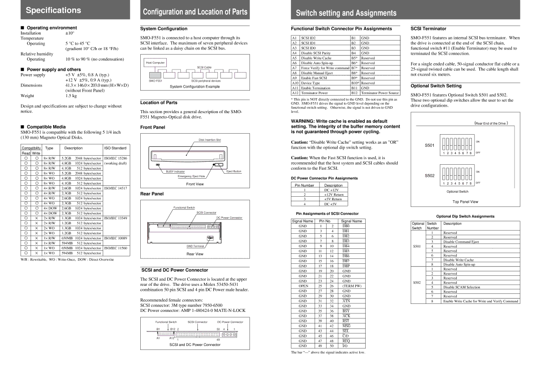
Optional Switch Setting
Top Panel View
Optional Dip Switch Assignments
Optional | Switch | Description |
Switch | Number |
|
| 1 | Reserved |
| 2 | Reserved |
| 3 | Disable Command Eject |
S501 | 4 | Reserved |
| 5 | Reserved |
| 6 | Reserved |
| 7 | Disable Write Cache |
| 8 | Disable Auto |
| 1 | Reserved |
| 2 | Reserved |
| 3 | Reserved |
S502 | 4 | Reserved |
| 5 | Disable SCAM Selection |
| 6 | Reserved |
| 7 | Reserved |
| 8 | Enable Write Cache for Write and Verify Command |
The bar