SAFETY CHECK-OUT
After correcting the original service problem, perform the following safety checks before releasing the set to the customer: Check the antenna terminals, metal trim, “metallized” knobs, screws, and all other exposed metal parts for AC leakage. Check leakage as described below.
LEAKAGE
The AC leakage from any exposed metal part to earth ground and from all exposed metal parts to any exposed metal part having a return to chassis, must not exceed 0.5 mA (500 microamperes). Leakage current can be measured by any one of three methods.
1.A commercial leakage tester, such as the Simpson 229 or RCA
2.A
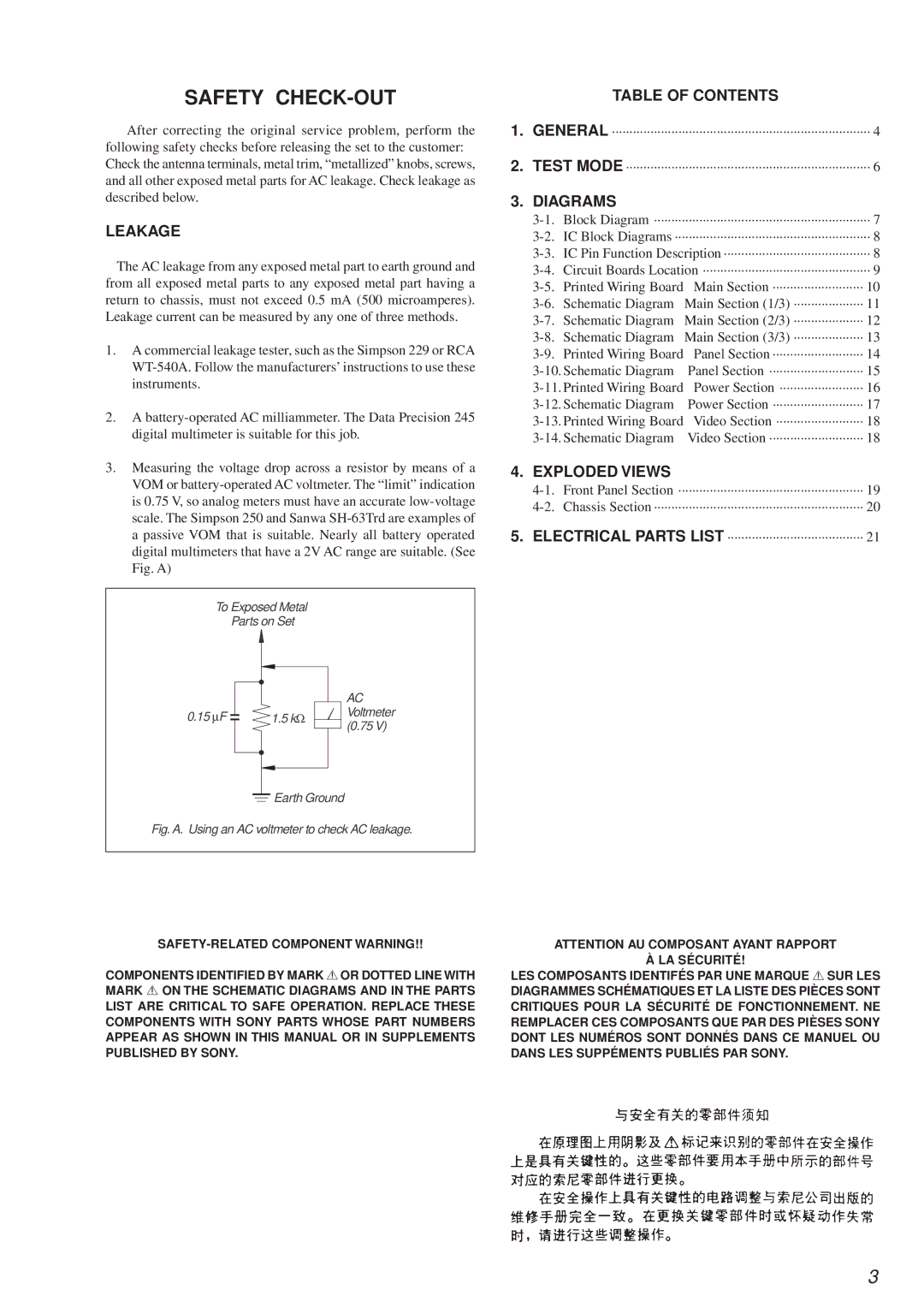
3.Measuring the voltage drop across a resistor by means of a VOM or
To Exposed Metal
Parts on Set
|
|
|
|
|
|
|
| AC |
|
|
|
|
|
|
|
| |
0.15 ∝F |
|
|
| 1.5 kΩ |
|
| Voltmeter | |
|
|
|
|
| ||||
|
|
|
|
| (0.75 V) | |||
|
|
|
|
|
|
|
| |
|
|
|
|
|
|
|
|
|
![]() Earth Ground
Earth Ground
Fig. A. Using an AC voltmeter to check AC leakage.
COMPONENTS IDENTIFIED BY MARK 0OR DOTTED LINE WITH MARK 0ON THE SCHEMATIC DIAGRAMS AND IN THE PARTS
LIST ARE CRITICAL TO SAFE OPERATION. REPLACE THESE COMPONENTS WITH SONY PARTS WHOSE PART NUMBERS APPEAR AS SHOWN IN THIS MANUAL OR IN SUPPLEMENTS PUBLISHED BY SONY.
TABLE OF CONTENTS
1.GENERAL ·························
2.TEST MODE ························
3.DIAGRAMS
Schematic Diagram | Main Section (2/3) ··········· | |
Schematic Diagram | Main Section (3/3) ··········· | |
Printed Wiring Board | Panel Section ············· | |
Panel Section ············· | ||
Power Section ············ | ||
Power Section ············ | ||
Video Section ············ | ||
Video Section ············· | ||
4.EXPLODED VIEWS
5.ELECTRICAL PARTS LIST ················
ATTENTION AU COMPOSANT AYANT RAPPORT À LA SÉCURITÉ!
LES COMPOSANTS IDENTIFÉS PAR UNE MARQUE 0SUR LES
DIAGRAMMES SCHÉMATIQUES ET LA LISTE DES PIÈCES SONT CRITIQUES POUR LA SÉCURITÉ DE FONCTIONNEMENT. NE REMPLACER CES COMPOSANTS QUE PAR DES PIÈSES SONY DONT LES NUMÉROS SONT DONNÉS DANS CE MANUEL OU DANS LES SUPPÉMENTS PUBLIÉS PAR SONY.
3