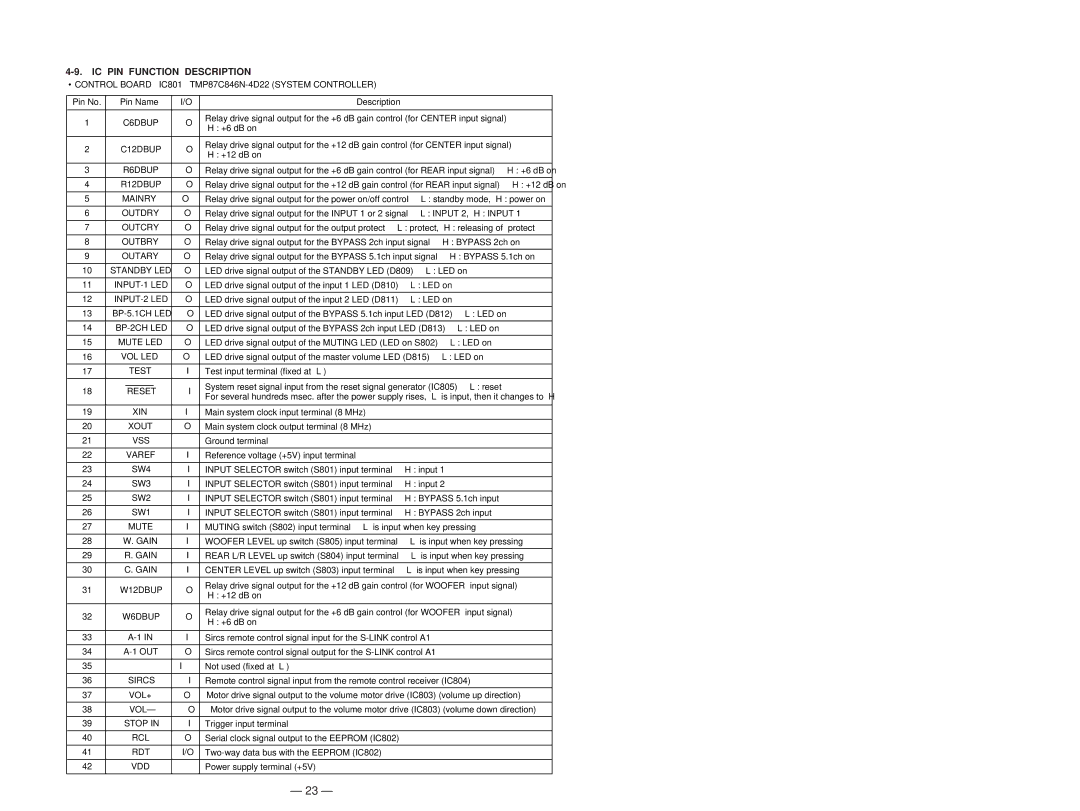
4-9. IC PIN FUNCTION DESCRIPTION

CONTROL BOARD IC801 TMP87C846N-4D22 (SYSTEM CONTROLLER)

Pin No.

Pin Name

I/O

Description


1

C6DBUP

O

Relay drive signal output for the +6 dB gain control (for CENTER input signal)


“H”: +6 dB on


2

C12DBUP

O

Relay drive signal output for the +12 dB gain control (for CENTER input signal)

“H”: +12 dB on


3

R6DBUP

O

Relay drive signal output for the +6 dB gain control (for REAR input signal) “H”: +6 dB on


4

R12DBUP

O

Relay drive signal output for the +12 dB gain control (for REAR input signal)

“H”: +12 dB on


5

MAINRY

O

Relay drive signal output for the power on/off control

“L”: standby mode, “H”: power on


6

OUTDRY

O

Relay drive signal output for the INPUT 1 or 2 signal

“L”: INPUT 2, “H”: INPUT 1


7

OUTCRY

O

Relay drive signal output for the output protect “L”: protect, “H”: releasing of

protect


8

OUTBRY

O

Relay drive signal output for the BYPASS 2ch input signal

“H”: BYPASS 2ch on


9

OUTARY

O

Relay drive signal output for the BYPASS 5.1ch input signal

“H”: BYPASS 5.1ch on


10

STANDBY LED

O

LED drive signal output of the STANDBY LED (D809) “L”: LED on


11

INPUT-1 LED

O

LED drive signal output of the input 1 LED (D810)


“L”: LED on


12

INPUT-2 LED

O

LED drive signal output of the input 2 LED (D811)


“L”: LED on


13

BP-5.1CH LED

O

LED drive signal output of the BYPASS 5.1ch input LED (D812)

“L”: LED on


14

BP-2CH LED

O

LED drive signal output of the BYPASS 2ch input LED (D813)

“L”: LED on


15

MUTE LED

O

LED drive signal output of the MUTING LED (LED on S802) “L”: LED on


16

VOL LED

O

LED drive signal output of the master volume LED (D815)

“L”: LED on


17


TEST

I

Test input terminal (fixed at “L”)


18


RESET

I

System reset signal input from the reset signal generator (IC805)

“L”: reset


For several hundreds msec. after the power supply rises, “L” is input, then it changes to “H”


19


XIN

I

Main system clock input terminal (8 MHz)


20


XOUT

O

Main system clock output terminal (8 MHz)


21


VSS

Ground terminal


22

VAREF

I

Reference voltage (+5V) input terminal


23


SW4

I

INPUT SELECTOR switch (S801) input terminal

“H”: input 1


24


SW3

I

INPUT SELECTOR switch (S801) input terminal

“H”: input 2


25


SW2

I

INPUT SELECTOR switch (S801) input terminal

“H”: BYPASS 5.1ch input


26


SW1

I

INPUT SELECTOR switch (S801) input terminal

“H”: BYPASS 2ch input


27


MUTE

I

MUTING switch (S802) input terminal “L” is input when key pressing


28

W. GAIN

I

WOOFER LEVEL up switch (S805) input terminal


“L” is input when key pressing


29

R. GAIN

I

REAR L/R LEVEL up switch (S804) input terminal


“L” is input when key pressing


30

C. GAIN

I

CENTER LEVEL up switch (S803) input terminal

“L” is input when key pressing


31

W12DBUP

O

Relay drive signal output for the +12 dB gain control (for WOOFER

input signal)

“H”: +12 dB on


32

W6DBUP

O

Relay drive signal output for the +6 dB gain control (for WOOFER

input signal)

“H”: +6 dB on


33


A-1 IN

I

Sircs remote control signal input for the S-LINK control A1


34

A-1 OUT

O

Sircs remote control signal output for the S-LINK control A1


35


I

Not used (fixed at “L”)


36


SIRCS

I

Remote control signal input from the remote control receiver (IC804)


37


VOL+

O

Motor drive signal output to the volume motor drive (IC803) (volume up direction)


38


VOL–

O

Motor drive signal output to the volume motor drive (IC803) (volume down direction)


39

STOP IN

I

Trigger input terminal


40


RCL

O

Serial clock signal output to the EEPROM (IC802)


41


RDT

I/O

Two-way data bus with the EEPROM (IC802)


42


VDD

Power supply terminal (+5V)


– 23 –

Page 17
Image 17
Sony TA-P9000ES service manual IC PIN Function Description, Control Board IC801 TMP87C846N-4D22 System Controller

TA-P9000ES specifications

The Sony TA-P9000ES is a high-performance preamplifier that has become a coveted piece of equipment for audio enthusiasts. Designed with precision and sophistication, the TA-P9000ES is a part of Sony's prestigious ES (Elevated Standard) series, known for its commitment to superior sound quality and durability.

One of the main features of the TA-P9000ES is its robust construction. Encased in a solid chassis, this preamplifier is designed to minimize resonance and electromagnetic interference, ensuring the cleanest signal possible. This attention to build quality not only enhances durability but also contributes to the overall performance of the unit.

At the heart of the TA-P9000ES is its advanced audio circuitry. Utilizing premium components and meticulous engineering, it delivers an exceptional auditory experience, capturing the nuances of each note with precision. The preamplifier supports a wide frequency response, allowing users to enjoy high-fidelity sound across various genres of music.

The TA-P9000ES boasts multiple connectivity options, making it versatile for different setups. It features balanced XLR inputs and outputs, ensuring optimal signal integrity over long cable runs. Additionally, RCA connectors are available for traditional setups, catering to a broader range of audio systems. The inclusion of digital inputs, such as optical and coaxial, enhances its compatibility with modern devices, allowing seamless integration into home theatre systems or digital music sources.

Another standout characteristic is its control flexibility. The TA-P9000ES comes equipped with a remote control, enabling users to adjust settings from across the room with ease. Furthermore, it features a user-friendly interface that simplifies navigation and configuration for achieving the desired audio profile.

In terms of technologies, the TA-P9000ES incorporates advanced digital signal processing (DSP) capabilities, allowing for precise tuning of audio output. The unit also supports various surround sound formats, accommodating audiophiles who seek an immersive experience while watching movies or playing games.

In summary, the Sony TA-P9000ES is a flagship preamplifier that combines construction quality, advanced audio circuitry, diverse connectivity options, and modern technologies. Its dedication to sound fidelity and user experience makes it a desirable choice for anyone serious about high-quality audio. As part of the ES series, it not only meets but often exceeds the expectations of audiophiles.