See the adjustment location from on page 22 for the ad- justment.
TAPE DECK SECTION |
| 0 dB=0.775 V |
|
|
|
Tape Speed Adjustment
Procedure:
1. Put the set into the FWD PB mode.
|
|
|
|
|
|
|
|
|
| speed checker | |||
|
|
|
|
|
|
|
|
|
|
| or | ||
test tape |
|
|
|
|
| frequency counter | |||||||
|
|
|
|
|
|
|
| ||||||
|
|
|
|
|
|
|
| ||||||
(3 kHz, 0 dB) |
|
|
|
| 10 kΩ |
|
| ||||||
|
|
|
| set |
|
|
|
|
| – + |
| ||
|
|
|
|
|
|
|
|
|
| ||||
|
|
|
|
|
|
|
|
|
| ||||
|
|
|
|
|
|
|
|
| |||||
|
|
|
|
|
|
|
|
|
|
|
| ||
|
|
|
|
|
| LINE OUT | |||||||
Specification: Constant speed |
|
|
|
|
|
|
| ||||||
|
|
|
|
| |||||||||
Speed checker |
|
|
| Frequency counter | |||||||||
|
|
|
| 2,955 to 3,075Hz | |||||||||
Adjustment Location: See page 22. |
|
|
|
|
| ||||||||
DOLBY Level Adjustment |
|
|
|
|
|
|
| ||||||
Setting: |
|
|
|
|
|
|
|
| |||||
Preset 3 (DOLBY) button | : |
| OFF | ||||||||||
SEL (BAS) button |
| : |
| Center | |||||||||
SEL (TRE) button |
| : |
| Center | |||||||||
SEL (BAL) button |
| : |
| Center | |||||||||
SEL (FAD) button |
| : |
| Center | |||||||||
SEL (VOL) button |
| : |
| Maximum | |||||||||
| : |
| OFF | ||||||||||
|
|
|
|
| main board |
| | ||||||
test tape | TP (DOLBY ) | | |||||||||||
| |||||||||||||
|
|
|
| level meter | |||||||||
|
|
|
|
| |||||||||
(400Hz, 0dB) |
|
|
|
|
| ||||||||
|
|
|
|
|
|
|
| ||||||
set | + | |
– | ||
| ||
| main board | |
| TP (GND) |
Procedure:
1.Put the set into the FWD PB mode.
2.Adjust RV231
Adjustment Location: See page 22.
TUNER SECTION
(XR-C450: E, Saudi Arabia model only)
0dB=1µV
Cautions during repair
When the tuner unit is defective, replace it by a new one because its internal block is difficult to repair.
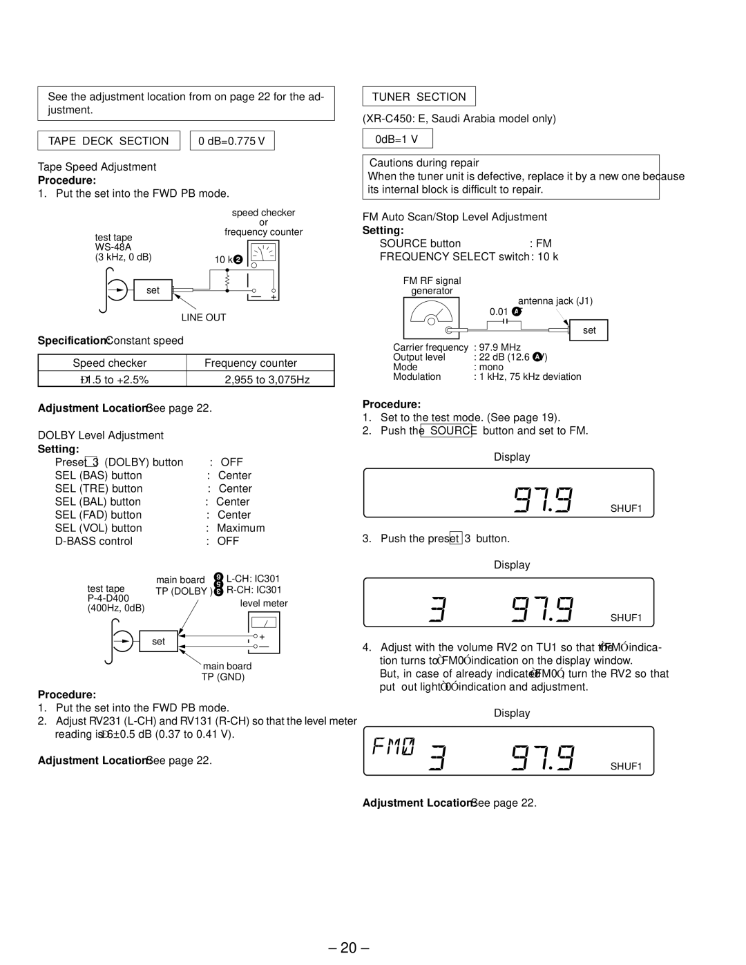
FM Auto Scan/Stop Level Adjustment
Setting:
SOURCE button |
|
|
|
|
|
|
|
| : FM | ||||
FREQUENCY SELECT switch : 10 k | |||||||||||||
FM RF signal |
|
|
|
|
|
|
|
|
|
|
| ||
| generator |
|
|
|
|
|
| antenna jack (J1) | |||||
|
|
|
|
|
|
|
|
| |||||
|
|
|
|
| 0.01 ∝ F | ||||||||
|
|
|
|
|
|
|
|
|
|
|
|
|
|
|
|
|
|
|
|
|
|
|
|
|
|
| set |
|
|
|
|
|
|
|
|
|
|
|
|
| |
|
|
| |||||||||||
Carrier frequency : 97.9 MHz | |||||||||||||
Output level | : 22 dB (12.6 ∝ V) | ||||||||||||
Mode | : mono | ||||||||||||
Modulation | : 1 kHz, 75 kHz deviation | ||||||||||||
Procedure:
1.Set to the test mode. (See page 19).
2.Push the SOURCE button and set to FM.
Display
FM
SHUF1
3.Push the preset 3 button.
Display
FM
SHUF1
4.Adjust with the volume RV2 on TU1 so that the “FM” indica- tion turns to “FM0” indication on the display window.
But, in case of already indicated “FM0”, turn the RV2 so that put out light “0” indication and adjustment.
Display
SHUF1
Adjustment Location: See page 22.
– 20 –