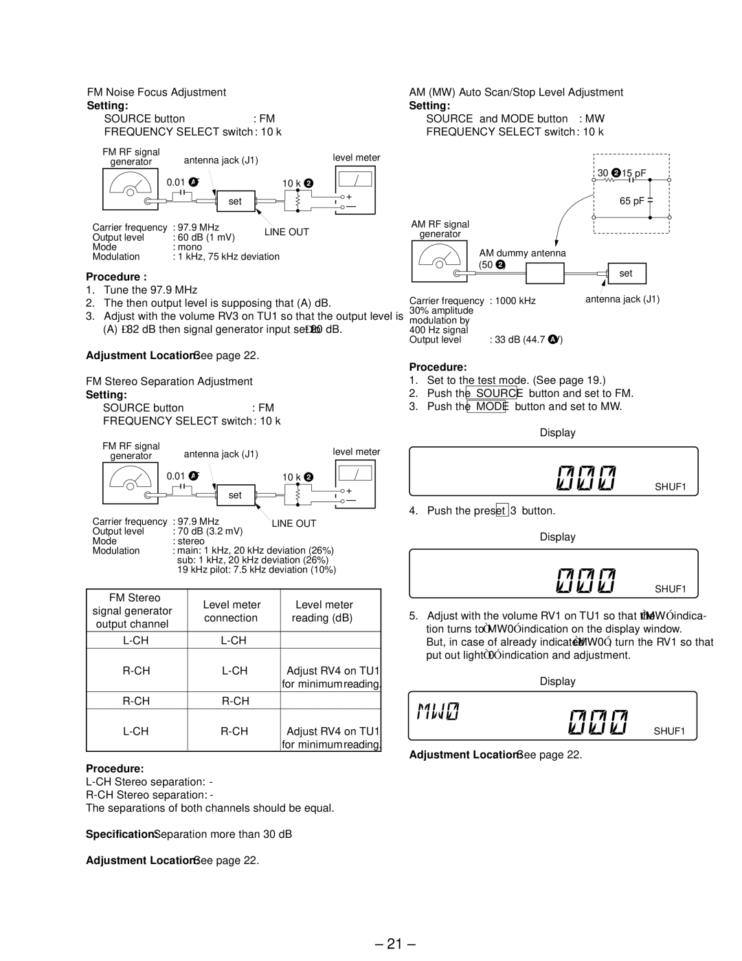
FM Noise Focus Adjustment
Setting:
SOURCE button | : FM |
FREQUENCY SELECT switch : 10 k
AM (MW) Auto Scan/Stop Level Adjustment
Setting:
SOURCE and MODE button : MW
FREQUENCY SELECT switch : 10 k
FM RF signal | antenna jack (J1) | level meter |
generator | ||
| 0.01 ∝ F | 10 k Ω |
| set | + |
| – | |
|
|
Carrier frequency | : 97.9 MHz | LINE OUT | |
Output level | : 60 dB (1 mV) | ||
| |||
Mode | : mono |
| |
Modulation | : 1 kHz, 75 kHz deviation | ||
Procedure :
1.Tune the 97.9 MHz
2.The then output level is supposing that (A) dB.
3.Adjust with the volume RV3 on TU1 so that the output level is
(A)
Adjustment Location: See page 22.
AM RF signal
generator
AM dummy antenna (50 Ω ) ![]()
![]()
Carrier frequency | : 1000 kHz |
30% amplitude |
|
modulation by |
|
400 Hz signal | : 33 dB (44.7 ∝ V) |
Output level |
30 Ω | 15 pF |
| 65 pF |
set
antenna jack (J1)
FM Stereo Separation Adjustment
Setting:
SOURCE button | : FM |
FREQUENCY SELECT switch : 10 k
FM RF signal | antenna jack (J1) | level meter |
generator | ||
| 0.01 ∝ F | 10 k Ω |
| set | + |
| – | |
|
|
Carrier frequency | : 97.9 MHz | LINE OUT | |||
Output level | : 70 dB (3.2 mV) |
|
| ||
Mode | : stereo |
|
| ||
Modulation | : main: 1 kHz, 20 kHz deviation (26%) | ||||
|
| sub: 1 kHz, 20 kHz deviation (26%) | |||
|
| 19 kHz pilot: 7.5 kHz deviation (10%) | |||
|
|
|
|
|
|
FM Stereo |
|
| Level meter |
| Level meter |
signal generator |
| ||||
connection |
| reading (dB) | |||
output channel |
|
| |||
|
|
|
| ||
|
|
| A | ||
|
|
|
|
|
|
|
|
|
|
| B |
|
|
| Adjust RV4 on TU1 | ||
|
|
|
|
| for minimum reading. |
|
|
|
|
|
|
|
|
| C | ||
|
|
|
|
|
|
|
|
|
|
| D |
|
|
| Adjust RV4 on TU1 | ||
|
|
|
|
| for minimum reading. |
Procedure:
The separations of both channels should be equal.
Specification: Separation more than 30 dB
Adjustment Location: See page 22.
Procedure:
1.Set to the test mode. (See page 19.)
2.Push the SOURCE button and set to FM.
3.Push the MODE button and set to MW.
Display
MW | 1 |
|
| SHUF1 |
4.Push the preset 3 button.
Display
MW 3 1 | SHUF1 |
5.Adjust with the volume RV1 on TU1 so that the “MW” indica- tion turns to “MW0” indication on the display window.
But, in case of already indicated “MW0”, turn the RV1 so that put out light “0” indication and adjustment.
Display
3 1 | SHUF1 |
Adjustment Location: See page 22.
– 21 –