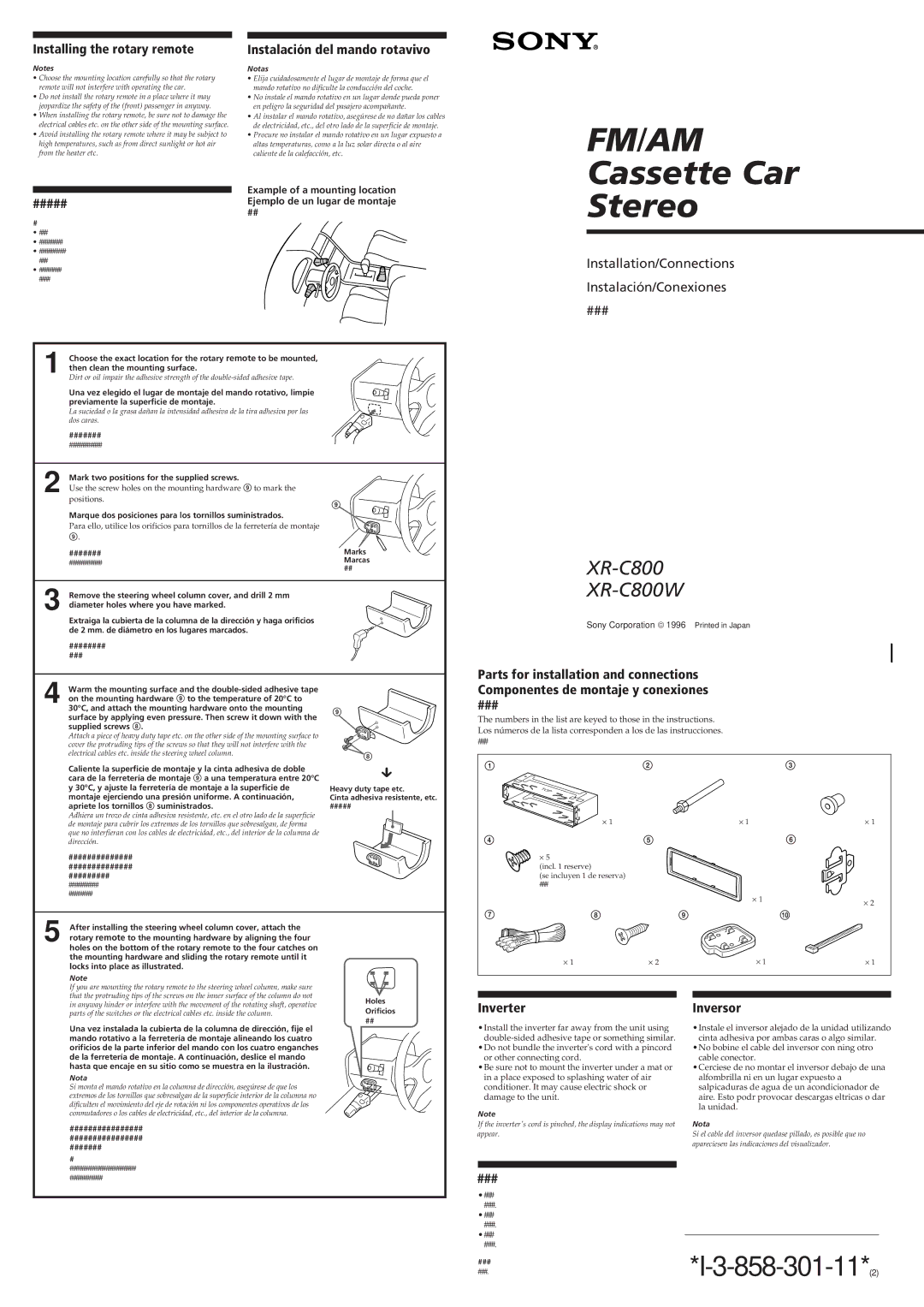
Installing the rotary remote | Instalación del mando rotavivo |
Notes | Notas |
• Choose the mounting location carefully so that the rotary | • Elija cuidadosamente el lugar de montaje de forma que el |
remote will not interfere with operating the car. | mando rotativo no dificulte la conducción del coche. |
• Do not install the rotary remote in a place where it may | • No instale el mando rotativo en un lugar donde pueda poner |
jeopardize the safety of the (front) passenger in anyway. | en peligro la seguridad del pasajero acompañante. |
• When installing the rotary remote, be sure not to damage the | • Al instalar el mando rotativo, asegúrese de no dañar los cables |
electrical cables etc. on the other side of the mounting surface. | de electricidad, etc., del otro lado de la superficie de montaje. |
• Avoid installing the rotary remote where it may be subject to | • Procure no instalar el mando rotativo en un lugar expuesto a |
high temperatures, such as from direct sunlight or hot air | altas temperaturas, como a la luz solar directa o al aire |
from the heater etc. | caliente de la calefacción, etc. |
Example of a mounting location
#####Ejemplo de un lugar de montaje
##
#
•###
•########
•#########
###
•########
####
| Choose the exact location for the rotary remote to be mounted, |
|
1 then clean the mounting surface. |
| |
| Dirt or oil impair the adhesive strength of the |
|
| Una vez elegido el lugar de montaje del mando rotativo, limpie |
|
| previamente la superficie de montaje. |
|
| La suciedad o la grasa dañan la intensidad adhesiva de la tira adhesiva por las |
|
| dos caras. |
|
| ####### |
|
2 | ########### |
|
Mark two positions for the supplied screws. |
| |
|
| |
| Use the screw holes on the mounting hardware 9 to mark the |
|
| positions. | 9 |
|
| |
| Marque dos posiciones para los tornillos suministrados. |
|
| Para ello, utilice los orificios para tornillos de la ferretería de montaje |
|
| 9. |
|
| ####### | Marks |
| ########### | Marcas |
| ## | |
|
| |
3 Remove the steering wheel column cover, and drill 2 mm diameter holes where you have marked.
Extraiga la cubierta de la columna de la dirección y haga orificios de 2 mm. de diámetro en los lugares marcados.
########
###
FM/AM
Cassette Car
Stereo
Installation/Connections
Instalación/Conexiones
###
XR-C800
XR-C800W
Sony Corporation © 1996 Printed in Japan
4 | Warm the mounting surface and the |
| |
| on the mounting hardware 9 to the temperature of 20°C to |
| 30°C, and attach the mounting hardware onto the mounting |
| surface by applying even pressure. Then screw it down with the |
| supplied screws 8. |
| Attach a piece of heavy duty tape etc. on the other side of the mounting surface to |
| cover the protruding tips of the screws so that they will not interfere with the |
| electrical cables etc. inside the steering wheel column. |
| Caliente la superficie de montaje y la cinta adhesiva de doble |
| cara de la ferretería de montaje 9 a una temperatura entre 20°C |
| y 30°C, y ajuste la ferretería de montaje a la superficie de |
| montaje ejerciendo una presión uniforme. A continuación, |
| apriete los tornillos 8 suministrados. |
| Adhiera un trozo de cinta adhesiva resistente, etc. en el otro lado de la superficie |
| de montaje para cubrir los extremos de los tornillos que sobresalgan, de forma |
| que no interfieran con los cables de electricidad, etc., del interior de la columna de |
| dirección. |
| ############## |
| ############## |
| ######### |
| ########## |
| ######## |
9
8
µ
Heavy duty tape etc.
Cinta adhesiva resistente, etc.
#####
Parts for installation and connections Componentes de montaje y conexiones
###
The numbers in the list are keyed to those in the instructions. Los números de la lista corresponden a los de las instrucciones.
###
1 | 2 | 3 |
× 1× 1× 1
4 |
| 5 |
| 6 |
| × 5 |
|
|
|
| (incl. 1 reserve) |
|
|
|
| (se incluyen 1 de reserva) |
|
|
|
| ### |
|
|
|
|
|
| × 1 | × 2 |
|
|
|
| |
7 | 8 | 9 |
| !¼ |
After installing the steering wheel column cover, attach the |
| |
5 rotary remote to the mounting hardware by aligning the four |
| |
holes on the bottom of the rotary remote to the four catches on |
| |
the mounting hardware and sliding the rotary remote until it |
| |
locks into place as illustrated. |
| |
Note |
| |
If you are mounting the rotary remote to the steering wheel column, make sure |
| |
that the protruding tips of the screws on the inner surface of the column do not | Holes | |
in anyway hinder or interfere with the movement of the rotating shaft, operative | ||
Orificios | ||
parts of the switches or the electrical cables etc. inside the column. | ||
## | ||
Una vez instalada la cubierta de la columna de dirección, fije el | ||
| ||
mando rotativo a la ferretería de montaje alineando los cuatro |
| |
orificios de la parte inferior del mando con los cuatro enganches |
| |
de la ferretería de montaje. A continuación, deslice el mando |
| |
hasta que encaje en su sitio como se muestra en la ilustración. |
| |
Nota |
| |
Si monta el mando rotativo en la columna de dirección, asegúrese de que los |
| |
extremos de los tornillos que sobresalgan de la superficie interior de la columna no |
| |
dificulten el movimiento del eje de rotación ni los componentes operativos de los |
| |
conmutadores o los cables de electricidad, etc., del interior de la columna. |
| |
################ |
| |
################ |
| |
####### |
| |
# |
| |
###################### |
| |
########### |
|
× 1 | × 2 | × 1 | × 1 |
Inverter |
| Inversor | |
•Install the inverter far away from the unit using |
| •Instale el inversor alejado de la unidad utilizando | |
| cinta adhesiva por ambas caras o algo similar. | ||
•Do not bundle the inverter's cord with a pincord |
| •No bobine el cable del inversor con ning otro | |
or other connecting cord. |
| cable conector. | |
•Be sure not to mount the inverter under a mat or |
| •Cerciese de no montar el inversor debajo de una | |
in a place exposed to splashing water of air |
| alfombrilla ni en un lugar expuesto a | |
conditioner. It may cause electric shock or |
| salpicaduras de agua de un acondicionador de | |
damage to the unit. |
| aire. Esto podr provocar descargas eltricas o dar | |
Note |
| la unidad. | |
|
|
| |
If the inverter's cord is pinched, the display indications may not |
| Nota | |
appear. |
| Si el cable del inversor quedase pillado, es posible que no | |
|
| apareciesen las indicaciones del visualizador. | |
|
|
|
|
|
|
|
|
### |
|
|
|
•### |
|
|
|
###. |
|
|
|
•### |
|
|
|
###. |
|
|
|
•### |
|
|
|
|
|
| |
###. |
| ||
### |
| ||
|
|
| |
###. |
|
|
|