Electrical Connections
All electrical connections to the GM29 are protected in compliance with the standard air (4 kV) and contact (8kV) discharge ESD tests, of EN 301
The modem uses the following industry standard connectors:
•RJ11
•RJ9
•SIM card reader
•FME male coaxial jack (antenna connector)
•
Power Connector
An RJ11
Connect positive power to VCC (pin 1) and the ground or negative to GND (pin 6). VCC and GND are reverse polarity and overvoltage protected
NOTE! Application of the supply voltage VCC, does not automatically switch on the modem.
Switch on is usually achieved by use of the TO_IN signal, which can be supplied by the host application. Alternatively the modem can be switched on at the same time that power is applied by
Similarly the host application can be designed to switch off the GM29 or perform a hard reboot of the modem's software by use of the HR_IN signal. Refer to “Switching Off the Modem” and “Resetting the Modem” on page 10 for additional information.
TO_IN and HR_IN are referenced to GND.
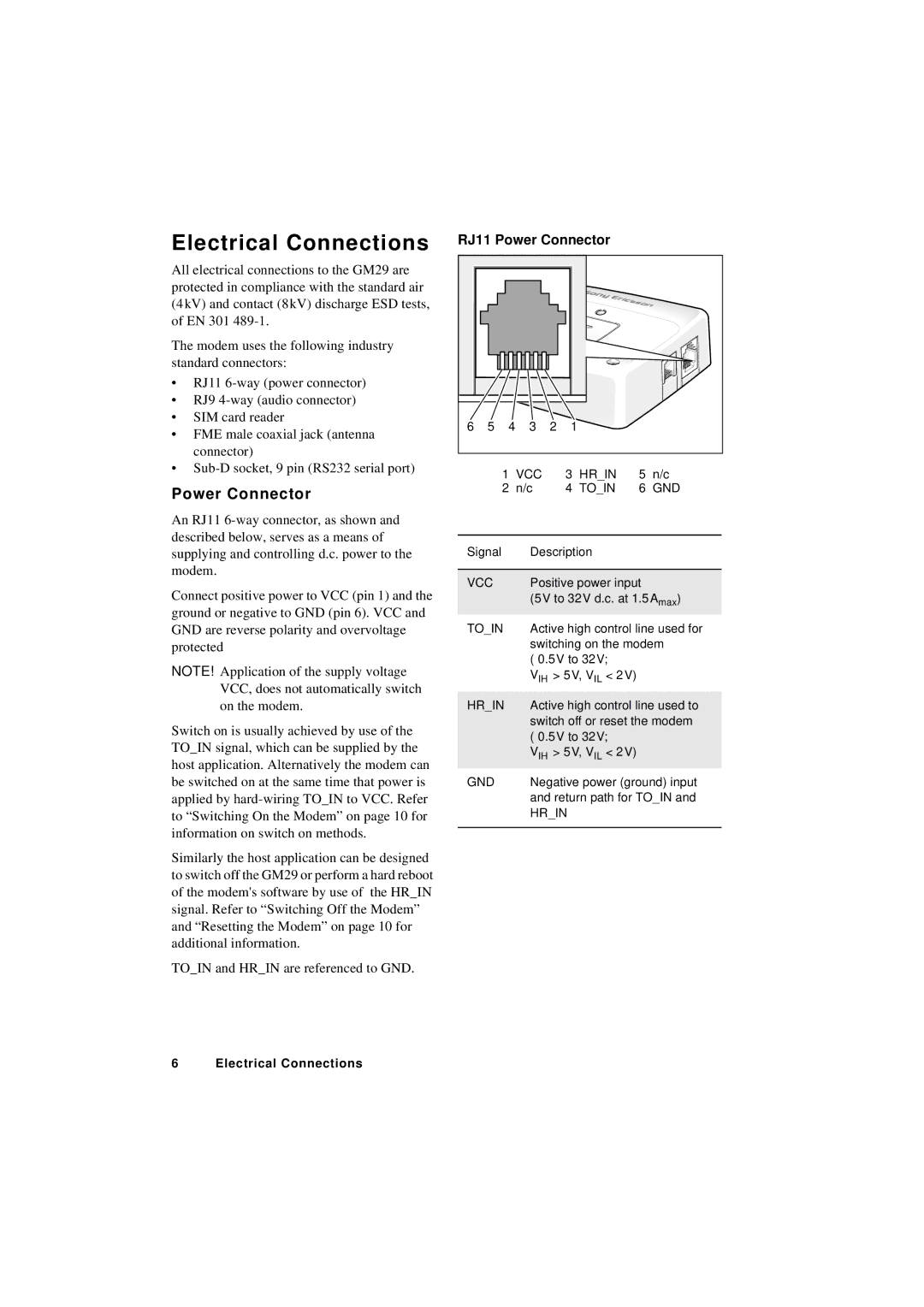
RJ11 Power Connector
6 | 5 | 4 | 3 | 2 | 1 |
1 VCC | 3 HR_IN | 5 n/c | |
2 n/c | 4 TO_IN | 6 GND | |
|
|
| |
Signal | Description |
| |
|
| ||
VCC | Positive power input | ||
| (5V to 32V d.c. at 1.5 Amax) | ||
TO_IN | Active high control line used for | ||
| switching on the modem | ||
|
| ||
| VIH > 5V, VIL < 2 V) |
| |
|
| ||
HR_IN | Active high control line used to | ||
| switch off or reset the modem | ||
|
| ||
| VIH > 5V, VIL < 2 V) |
| |
GND | Negative power (ground) input | ||
| and return path for TO_IN and | ||
| HR_IN |
| |
|
|
|
|
6 Electrical Connections