
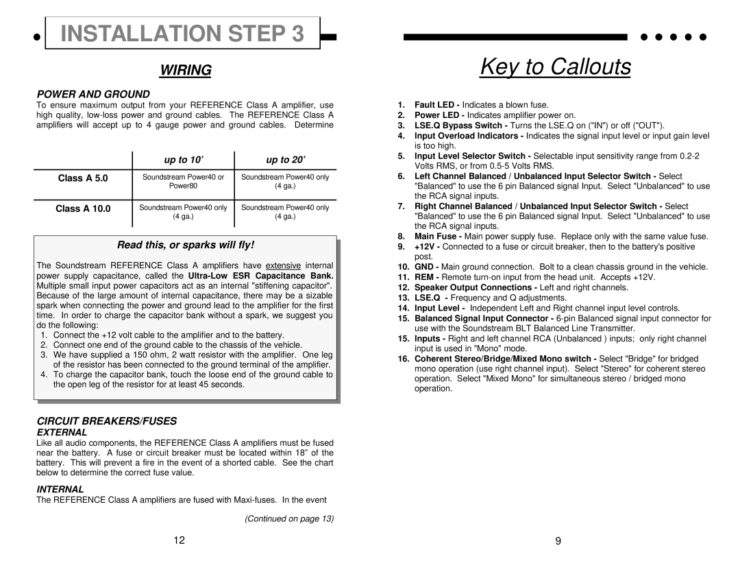
Class A 10.0, Class A 5.0 specifications
Soundstream Technologies has established itself as a frontrunner in the field of high-fidelity audio equipment with its innovative Class A amplifiers, most notably the Class A 10.0 and Class A 5.0. These amplifiers exemplify their commitment to superior sound quality and advanced engineering.The Class A 10.0 amplifier is designed for audiophiles seeking unparalleled audio performance. It boasts a remarkable power output of 100 watts per channel, ensuring that even the most demanding speakers can be driven effortlessly. One of the standout features of the Class A 10.0 is its true Class A operation, meaning it operates at all times in the Class A range, delivering a warm and rich sound signature. This type of operation reduces distortion significantly, allowing for a more authentic reproduction of audio across various frequencies.
In contrast, the Class A 5.0 amplifier caters to smaller setups without compromising on sound fidelity. With an output of 50 watts per channel, it is ideally suited for compact systems or near-field monitoring applications. Despite its smaller size, the Class A 5.0 still utilizes Class A circuitry, promising a similarly lush audio experience.
Both models integrate innovative technologies to enhance performance. They utilize high-quality components, including carefully-selected capacitors and low-noise transistors, which contribute to the amplifiers' exceptional sound clarity. The advanced thermal management system ensures that these amplifiers maintain optimal operating temperatures, enhancing reliability and durability during extended listening sessions.
Additionally, the integrated power supply in both amplifiers is designed to minimize voltage fluctuations, further refining audio output. This feature is crucial for preserving the integrity of the sound, especially during peaks in musical dynamics. Each model also features a fully balanced input, which significantly reduces noise interference from external sources.
In summary, the Soundstream Technologies Class A 10.0 and Class A 5.0 amplifiers are perfect embodiments of the brand's dedication to delivering exceptional audio performance. With their Class A operation, powerful outputs, and advanced technological features, these amplifiers stand out in a competitive market, appealing to audiophiles and casual listeners alike. Whether for a home theater system or a studio setup, these amplifiers guarantee a superior listening experience characterized by clarity, warmth, and minimal distortion.