Step 4. Attach Connectors
This section tells how to connect internal peripherals and power supply to the Motherboard.
Internal peripherals include IDE devices (HDD,
For more details on how to connect internal and external peripherals to your new
Connectors and Plug-ins
|
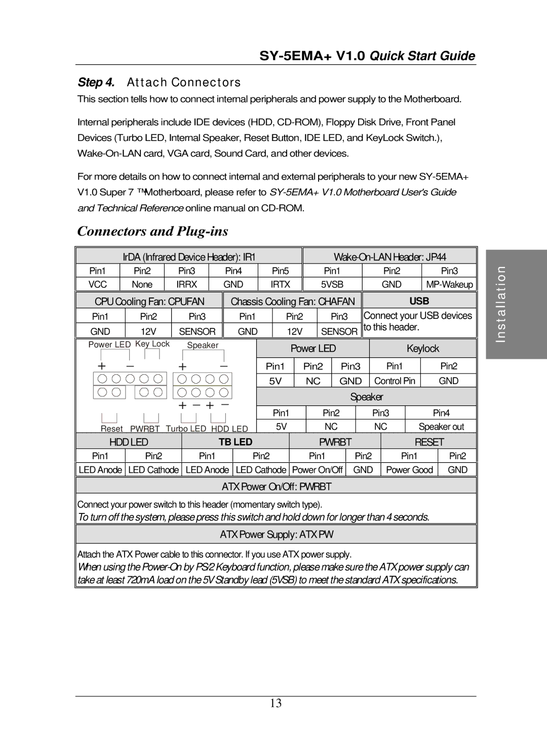
| IrDA (Infrared Device Header): IR1 |
|
|
| ||||||||
| Pin1 | Pin2 | Pin3 |
|
| Pin4 | Pin5 | Pin1 |
| Pin2 |
| Pin3 |
|
| VCC | None | IRRX |
| GND | IRTX | 5VSB |
| GND |
|
| ||
| CPU Cooling Fan: CPUFAN |
|
| Chassis Cooling Fan: CHAFAN |
|
| USB |
| |||||
Pin1 | Pin2 |
| Pin3 | Pin1 |
| Pin2 |
| Pin3 | Connect your USB devices | |
GND | 12V |
| SENSOR | GND |
| 12V | SENSOR to this header. | |||
Power LED Key Lock | Speaker |
|
| Power LED | Keylock | |||||
+ | _ |
| + | _ | Pin1 | Pin2 | Pin3 | Pin1 | Pin2 | |
|
|
| ||||||||
|
|
|
|
| 5V |
| NC | GND | Control Pin | GND |
|
|
| + _ + | _ |
|
|
| Speaker |
| |
|
|
| Pin1 | Pin2 | Pin3 | Pin4 | ||||
|
|
|
|
| ||||||
Reset | PWRBT | Turbo LED HDD LED | 5V |
| NC | NC | Speaker out | |||
| HDD LED |
| TB LED |
| PWRBT |
|
| RESET |
|
| ||||
| Pin1 | Pin2 |
| Pin1 | Pin2 |
| Pin1 |
| Pin2 |
| Pin1 |
| Pin2 |
|
| LED Anode | LED Cathode |
| LED Anode | LED Cathode |
| Power On/Off |
| GND |
| Power Good |
| GND |
|
ATX Power On/Off: PWRBT
Connect your power switch to this header (momentary switch type).
To turn off the system, please press this switch and hold down for longer than 4 seconds.
ATX Power Supply: ATX PW
Attach the ATX Power cable to this connector. If you use ATX power supply.
When using the
Installation
13