Installation
Step 5. Configure Memory
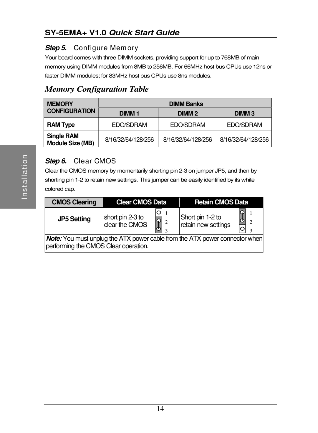
Your board comes with three DIMM sockets, providing support for up to 768MB of main memory using DIMM modules from 8MB to 256MB. For 66MHz host bus CPUs use 12ns or faster DIMM modules; for 83MHz host bus CPUs use 8ns modules.
Memory Configuration Table
MEMORY |
| DIMM Banks |
| |
CONFIGURATION | DIMM 1 | DIMM 2 | DIMM 3 | |
| ||||
RAM Type | EDO/SDRAM | EDO/SDRAM | EDO/SDRAM | |
|
|
|
| |
Single RAM | 8/16/32/64/128/256 | 8/16/32/64/128/256 | 8/16/32/64/128/256 | |
Module Size (MB) | ||||
|
|
|
Step 6. Clear CMOS
Clear the CMOS memory by momentarily shorting pin
CMOS Clearing | Clear CMOS Data |
| Retain CMOS Data |
| ||||
JP5 Setting | short pin |
| 1 |
| Short pin |
|
| 1 |
|
|
|
| |||||
| 2 |
|
|
| 2 | |||
|
| |||||||
| clear the CMOS |
|
| retain new settings |
|
| ||
|
| 3 |
|
|
| 3 | ||
|
|
|
|
|
|
| ||
|
|
|
|
|
|
|
|
|
Note: You must unplug the ATX power cable from the ATX power connector when performing the CMOS Clear operation.
14
