Step 2. Connections to the Motherboard
This section tells how to connect internal peripherals and the power supply to the Motherboard.
The internal peripherals consist of IDE devices (HDD,
For more details on connecting internal and external peripherals to your new
Connectors and Plug-ins
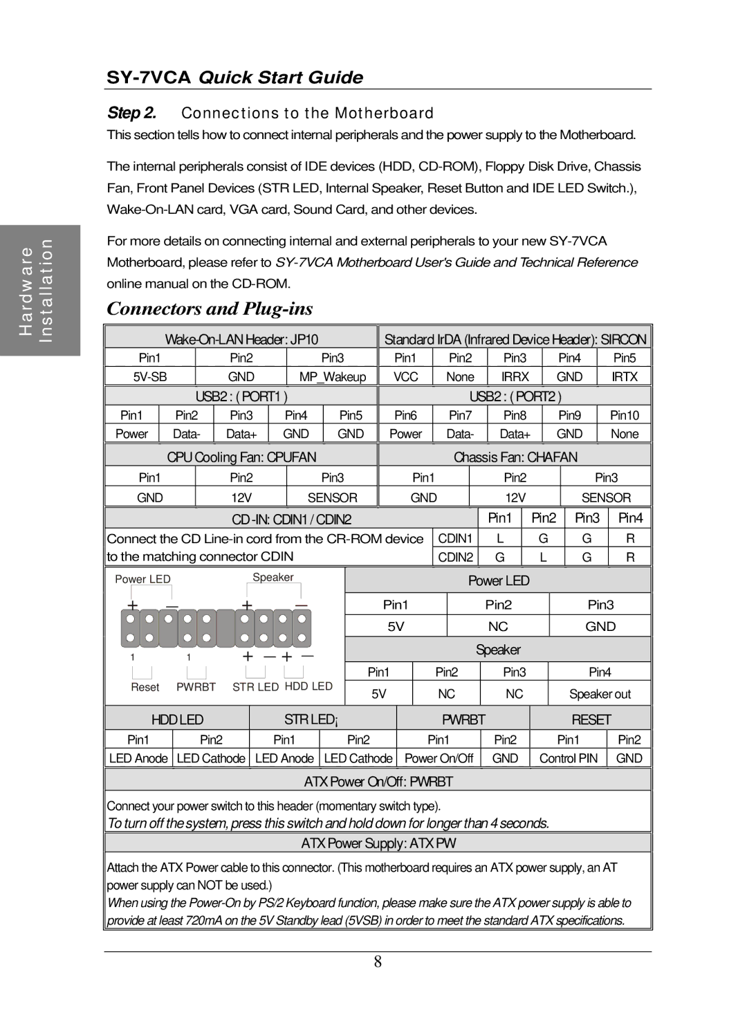
Wake-On-LAN Header: JP10
Pin1 | Pin2 | Pin3 |
GND | MP_Wakeup |
USB2 : ( PORT1 )
Pin1 Pin2 Pin3 Pin4 Pin5
Power Data- Data+ GND GND
CPU Cooling Fan: CPUFAN
Pin1 | Pin2 | Pin3 |
GND | 12V | SENSOR |
Standard IrDA (Infrared Device Header): SIRCON
Pin1 |
| Pin2 | Pin3 | Pin4 |
| Pin5 | ||
VCC |
| None | IRRX | GND |
| IRTX | ||
|
|
| USB2 : ( PORT2 ) |
|
| |||
Pin6 |
| Pin7 | Pin8 | Pin9 |
| Pin10 | ||
Power |
| Data- | Data+ | GND |
| None | ||
|
| Chassis Fan: CHAFAN |
|
| ||||
Pin1 |
|
| Pin2 |
|
| Pin3 | ||
GND |
|
| 12V |
| SENSOR | |||
|
|
| CD |
| Pin1 | Pin2 | Pin3 | Pin4 | |||
Connect the CD | CDIN1 | L | G | G | R | ||||||
to the matching connector CDIN |
|
| CDIN2 | G | L | G | R | ||||
Power LED |
| Speaker |
|
| Power LED |
|
|
| |||
+ | _ | + | _ |
| Pin1 |
| Pin2 |
| Pin3 |
| |
|
|
|
|
|
|
| |||||
|
|
|
|
|
| 5V |
| NC |
| GND | |
1 |
| 1 | + _ + _ |
|
|
| Speaker |
|
|
| |
|
|
|
|
|
| Pin1 | Pin2 | Pin3 |
| Pin4 |
|
Reset | PWRBT | STR LED HDD LED | 5V | NC | NC |
| Speaker out | ||||
|
|
|
|
|
|
| |||||
| HDD LED |
| STR LED¡ ° | PWRBT |
| RESET |
| ||||
Pin1 |
| Pin2 |
| Pin1 |
| Pin2 | Pin1 | Pin2 |
| Pin1 | Pin2 |
LED Anode | LED Cathode LED Anode | LED Cathode Power On/Off | GND | Control PIN | GND | ||||||
ATX Power On/Off: PWRBT
Connect your power switch to this header (momentary switch type).
To turn off the system, press this switch and hold down for longer than 4 seconds.
ATX Power Supply: ATX PW
Attach the ATX Power cable to this connector. (This motherboard requires an ATX power supply, an AT power supply can NOT be used.)
When using the
8