COMMAND POST ADJUSTABLE HEIGHT SEAT POST
INSTALLATION GUIDE
INTRODUCTION
The Command Post seat post provides riders with a way to adjust their saddle height without tools. Although created by the Specialized Suspension team, the Command Post is NOT a suspension seat post.
Visit a Specialized authorized dealer if you have any doubt regarding your mechanical proficiency and/or ability to install this product. Specialized recommends that the Command Post be installed by a qualified bicycle mechanic.
Please read and understand all the warnings. Failure to follow a warning may result in a catastrophic failure of the Command Post, resulting in serious personal injury or death. This phrase may not be repeated in connection with each and every warning.
TERMINOLOGY
Power position: When the Command Post is at full height. Used when full power is needed, such as climbing a long, steep hill or riding a smooth, flat section. This position provides the full 100mm of available seat post height.
Cruiser position: When the Command Post is in the middle position. Used for pedaling on undulating terrain. This position is 35mm below the Power position.
Descender position: When the Command Post is at its lowest position. Used for riding downhill/freeride terrain. This position is 100mm below the Power position.
Remote Lever: Used to actuate the Command Post.
INSTALLATION
Take the following items into consideration before installing and using the Command Post.
The air pressure in the Command Post is factory set to 25 psi. Air pressure determines the speed at which the Command Post rises. See SETUP AND USE for more information.
The Command Post is 30.9mm in diameter. Prior to installation, ensure that this diameter conforms to the diameter of the seat tube.
WARNING! Incorrect sizing interface can result in Command Post slippage or failure, causing serious personal injury or death.
The Command Post should not have any play inside the frame.
The Command Post should slide into the seat tube in a straight, smooth fashion.
The seat collar should be positioned so that the slot faces forward to minimize dirt contamination from the rear wheel.
If the Command Post exhibits any fit and/or torque issues, it is recommended that the fit tolerance be verified by a Specialized Authorized Dealer.
INSTALLING THE COMMAND POST
1.On
2.Slide the Command Post into the seat tube.
3.Adjust the Command Post to approximate height for proper leg extension. The Command Post ships in the Power (full height) position. While in the Power position, determine saddle height like you would a standard seat post.
i | Leave the Command Post in the Power position during installation. This will |
ensure that the cable housing is at the correct length. |
4.Adjust seat collar torque to recommended setting (see fig. 2).
i | IMPORTANT! Recommended torques in this manual are specific for the Command |
Post. Consult the bicycle owner’s manual for recommended torque. Always use | |
| lower torque recommendation. |
WARNING! Only use seat collars approved by Specialized with the Command Post. Use of an unapproved seat collar may result in slippage and potential damage of the Command Post.
The following 30.9 collars have been tested and recommended: Specialized fixed and Q/R collars
Salsa
Please visit www.specialized.com for future approved collars.
NOTE: Do not overtighten. Use only hand pressure on Q/R lever. Only use enough tension to keep the post from slipping. If you are having slipping issues, friction compound pastes or talc powder can be used on aluminum and carbon frames.
WARNING! Seat collar torque requirements can vary depending on the specific frame and seat clamp used. Exceeding the max specified torque limit (see fig. 2) can result in damage to the Command Post and/or frame. Consult an authorized dealer for additional information.
1
NUT | BOLT |
WEDGE | RAIL |
NUT AND RAIL CLAMP ASSEMBLY | CLAMP |
ALIGN ARROWS TAB | SLOT |
CARBONNON-CARBON
FRAMESFRAMES
• SEAT COLLAR I.D.
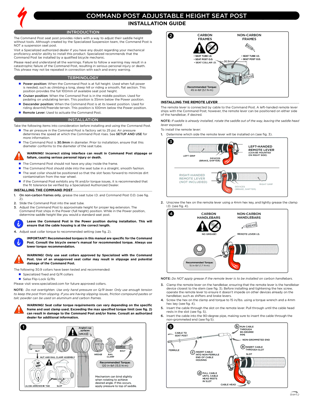
INSTALLING THE REMOTE LEVER
The remote lever is connected by cable to the Command Post. A
NOTE: If saddle is already installed, rotate the saddle out of the way, leaving the saddle head lever exposed.
To install the remote lever:
1.Determine which side the remote lever will be installed on (see fig. 3).
3
| |
| REMOTE LEVER |
| (CAN BE MOUNTED |
LEFT GRIP | ON RIGHT SIDE) |
| |
DEVICES |
|
(BRAKE, SHIFTER) |
|
|
|
REMOTE LEVER |
|
(NOT INCLUDED) | RIGHT GRIP |
| |
| DEVICES |
| (BRAKE, SHIFTER) |
2.Unscrew the hex on the remote lever using a 4mm hex key, and lightly grease the clamp I.D. (see fig. 4).
4 | CARBON |
|
| HANDLEBARS | HANDLEBARS |
| NO GREASE! | REMOTE LEVER I.D. |
| 4MM |
|
| 15 |
|
NOTE: Do NOT apply grease if the remote lever is to be installed on carbon handlebars.
3.Clamp the remote lever on the handlebar, ensuring that the remote lever is the handlebar device closest to the stem (see fig. 3). Before installing and tightening the hex screw, operate the remote lever to ensure it doesn’t impede on other devices already on the handlebar, such as shifters and brake levers.
4.Screw the hex on the clamp and torque to 15 in/lbs. using a torque wrench and a 4mm hex key (see fig. 4).
5.Insert the cable through the slot on the remote lever. Pull through until the cable head rests in the slot (see fig. 5).
6.Insert the cable into the
5 |
|
| b | RUN CABLE | |
|
|
|
| THROUGH | |
CABLE TO |
|
|
| ||
|
|
| PIPE |
| |
SEAT POST |
|
|
|
| |
|
|
|
|
| |
|
|
|
| ||
|
|
|
| a | INSERT CABLE |
FERRULE | c | INSERT CABLE |
| THROUGH SLOT | |
|
| SLOT | |||
|
| INTO |
| ||
|
|
|
| ||
|
| END OF CABLE |
|
| |
|
| HOUSING |
|
| |
|
| d | PULL CABLE |
|
|
|
|
| UNTIL CABLE |
|
|
|
|
| HEAD RESTS |
|
|
|
|
| IN SLOT |
|
|
|
|
| CABLE HEAD |
|
|
(con’t.)