7.Insert the cable into the
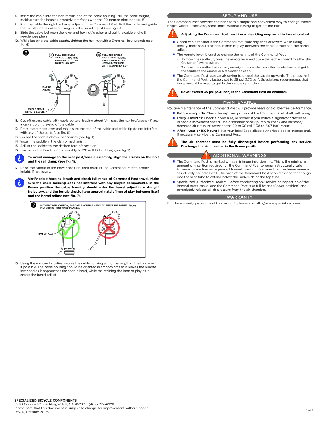
8.Run the cable through the barrel adjust on the Command Post. Pull the cable and guide the ferrule on the cable housing into the barrel adjust (see fig. 6).
9.Slide the cable between the lever and hex nut/washer and pull the cable end with needlenose pliers.
10.While keeping the cable taught, tighten the hex nut with a 3mm hex key wrench (see fig. 6).
6 | a | PULL THE CABLE | b | PULL THE CABLE |
| ||||
|
| AS YOU GUIDE THE |
| TIGHT WITH PLIERS, |
|
| FERRULE INTO THE |
| THEN TIGHTEN THE |
|
| BARREL ADJUST |
| HEX NUT/WASHER |
|
|
|
| WITH A 3MM HEX KEY |
| BARREL |
|
|
|
| ADJUST |
|
|
|
|
|
| 3MM |
|
| CABLE FROM |
|
|
|
REMOTE LEVER |
|
|
| |
11.Cut off excess cable with cable cutters, leaving about 1/4” past the hex key/washer. Place a cable tip on the end of the cable.
12.Press the remote lever and make sure the end of the cable and cable tip do not interfere with any of the parts (see fig. 6).
13.Grease the saddle clamp mechanism (see fig. 1).
14.Install the saddle in the clamp mechanism.
15.Adjust the saddle to the desired
16.Torque saddle head clamp assembly to 120
i | To avoid damage to the seat post/saddle assembly, align the arrows on the bolt |
| and the rail clamp (see fig. 1). |
17.Raise the saddle to the Power position, then readjust the Command Post to proper height, if necessary.
i | Verify cable housing length and check full range of Command Post travel. Make | ||
sure the cable housing does not interfere with any bicycle components. In the | |||
| |||
| Power position the cable housing should enter the barrel adjust in a straight | ||
| trajectory, and the ferrule should have approximately 1mm of play between itself | ||
| and the barrel adjust (see fig. 7). | ||
| 7 | IN THE POWER POSITION, THE CABLE HOUSING NEEDS TO ENTER THE BARREL ADJUST | |
|
| IN A STRAIGHTFORWARD MANNER. | |
SETUP AND USE
The Command Post provides the rider with a simple and convenient way to change saddle height without tools and, sometimes, without having to get off the bike.
Adjusting the Command Post position while riding may result in loss of control.
Check cable tension if the Command Post suddenly rises or lowers while riding. Ideally, there should be about 1mm of play between the cable ferrule and the barrel adjust.
The remote lever is used to change the height of the Command Post:
»»To move the saddle up, press the remote lever and guide the saddle upward to either the Cruiser or Power position.
»»To move the saddle down, slowly unweight the saddle, press the remote lever and guide the saddle to the Cruiser or Descender position.
The Command Post uses an air spring to propel the saddle upwards. The pressure in the Command Post is factory set to 25 psi (1.72 bar). Specialized recommends that body weight be used to guide the saddle up or down.
Never exceed 35 psi (2.41 bar) in the Command Post air chamber.
MAINTENANCE
Routine maintenance of the Command Post will provide years of
Every 3 months: Check air pressure, or sooner if you notice a significant decrease in saddle movement speed. Use a standard shock pump to check and increase/ decrease air pressure between the 20 to 30 psi (1.38 to 2.07 bar) range.
After 1 year or 150 hours: Have your local Specialized authorized dealer inspect and, if necessary, service the Command Post.
The air chamber must be fully discharged before performing any service. Discharge the air chamber in the Power position.
 ADDITIONAL WARNINGS
The Command Post is marked with a minimum insertion line. This is the minimum amount of insertion required for the Command Post to remain structurally safe. However, some frames require additional insertion to ensure that the frame remains structurally sound as well. The base of the Command Post should extend far enough into the seat tube to extend below the underside of the top tube.
Specialized Authorized Dealers: Before conducting any service or inspection of the internal parts, make sure the Command Post is at full height (Power position) and completely release all air pressure from the air chamber.
WARRANTY
For the warranty provisions of this product, please visit http://www.specialized.com.
1MM OF PLAY
18.Using the enclosed
SPECIALIZED BICYCLE COMPONENTS |
| |
15130 Concord Circle, Morgan Hill, CA 95037 (408) |
| |
Please note that this document is subject to change for improvement without notice. | 2 of 2 | |
Rev. D, October 2008 | ||
|