AL 24/28/32 - A/M Series
Auto Levels
User Guide
•
www.trimble.com
How to Use the Instrument
Setting Up the Instrument
1.Set up the tripod at a height appropriate for your use.
Note: Make sure the tripod is stable and the tripod head is relatively level.
2.Attach the instrument to the tripod.
3.Level the instrument using the circular level as a reference.
4.Focus the telescope crosshairs by turning the crosshairs’ focusing ring.
Aligning the Instrument
1.Align the telescope to the grade rod using the sighting guides.
2.Turn the focusing knob to bring the grade rod into sharp focus. Precisely sight the center of the grade rod in the telescope crosshairs using the horizontal tangent knob.
3.Check for parallax shift.
Note: No parallax exists if the crosshairs and the grade rod graduations remain in coincidence even when you change your viewing angle (move your eye up/down and left/right in front of the eyepiece).
Note: After the bubble in the circular level has been centered, the compensator corrects residual
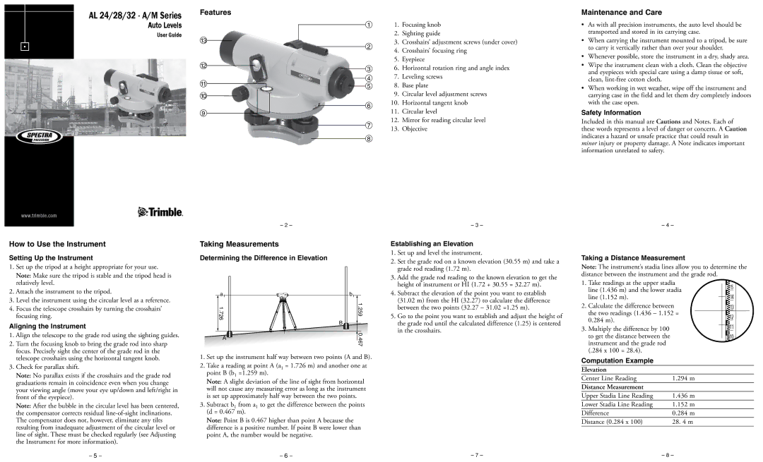
Features
| 1 |
13 | 2 |
| |
12 | 3 |
|
4
11![]()
![]() 5
5
10
6
9
7
8
– 2 –
Taking Measurements
Determining the Difference in Elevation
a1 | b1 |
1.726 | 1.259 |
| B |
A | 0.467 |
|
1.Set up the instrument half way between two points (A and B).
2.Take a reading at point A (a1 = 1.726 m) and another one at point B (b1 =1.259 m).
Note: A slight deviation of the line of sight from horizontal will not cause any measuring error as long as the instrument is set up approximately half way between the two points.
3.Subtract b1 from a1 to get the difference between the points (d = 0.467 m).
Note: Point B is 0.467 higher than point A because the difference is a positive number. If point B were lower than point A, the number would be negative.
01. Focusing knob
02. Sighting guide
03. Crosshairs’ adjustment screws (under cover)
04. Crosshairs’ focusing ring
05. Eyepiece
06. Horizontal rotation ring and angle index
07. Leveling screws
08. Base plate
09. Circular level adjustment screws
10.Horizontal tangent knob
11.Circular level
12.Mirror for reading circular level
13.Objective
– 3 –
Establishing an Elevation
1.Set up and level the instrument.
2.Set the grade rod on a known elevation (30.55 m) and take a grade rod reading (1.72 m).
3.Add the grade rod reading to the known elevation to get the height of instrument or HI (1.72 + 30.55 = 32.27 m).
4.Subtract the elevation of the point you want to establish (31.02 m) from the HI (32.27) to calculate the difference between the two points (32.27 – 31.02 =1.25 m).
5.Go to the point you want to establish and adjust the height of the grade rod until the calculated difference (1.25) is centered in the crosshairs.
Maintenance and Care
•As with all precision instruments, the auto level should be transported and stored in its carrying case.
•When carrying the instrument mounted to a tripod, be sure to carry it vertically rather than over your shoulder.
•Whenever possible, store the instrument in a dry, shady area.
•Wipe the instrument clean with a cloth. Clean the objective and eyepieces with special care using a damp tissue or soft, clean,
•When working in wet weather, wipe off the instrument and carrying case in the field and let them dry completely indoors with the case open.
Safety Information
Included in this manual are Cautions and Notes. Each of these words represents a level of danger or concern. A Caution indicates a hazard or unsafe practice that could result in minor injury or property damage. A Note indicates important information unrelated to safety.
– 4 –
Taking a Distance Measurement
Note: The instrument’s stadia lines allow you to determine the distance between the instrument and the grade rod.
1. Take readings at the upper stadia |
|
|
|
|
|
|
|
|
| 15 |
| |||
line (1.436 m) and the lower stadia |
|
|
|
|
|
|
|
|
|
| ||||
|
|
|
|
|
|
|
|
|
|
| ||||
line (1.152 m). |
|
|
|
|
|
|
|
|
|
| 14 |
| ||
|
|
|
|
|
|
|
|
|
|
|
| |||
|
|
|
|
|
|
|
|
|
|
|
| |||
2. Calculate the difference between |
|
|
|
|
| |||||||||
|
|
|
| |||||||||||
|
|
|
| 13 |
| |||||||||
|
|
|
|
|
|
|
|
|
| |||||
the two readings (1.436 – 1.152 = |
|
|
|
|
|
|
|
|
|
|
|
|
| |
|
|
|
|
|
|
|
|
|
| 12 |
| |||
|
|
|
|
|
|
|
|
|
|
| ||||
0.284 m). |
|
|
|
|
|
|
| |||||||
|
|
|
|
|
|
|
|
|
|
|
| |||
|
|
|
|
|
|
|
|
|
| 11 |
| |||
3. Multiply the difference by 100 |
|
|
|
|
|
|
|
|
|
| ||||
|
|
|
|
|
|
|
|
| ||||||
|
|
|
|
|
|
|
|
|
| |||||
|
|
|
|
|
|
|
|
|
|
| ||||
|
|
|
|
|
|
|
|
|
|
| ||||
to get the distance between the |
|
|
|
|
|
|
| 10 |
| |||||
|
|
|
|
|
|
| ||||||||
|
|
|
|
|
|
|
| |||||||
instrument and the grade rod |
|
|
|
|
|
|
|
|
|
|
|
|
|
|
(.284 x 100 = 28.4). |
|
|
|
|
|
|
|
|
|
|
|
|
|
|
Computation Example |
|
|
|
|
|
|
|
|
|
|
|
|
|
|
Elevation |
|
|
|
|
|
|
|
|
|
|
|
|
|
|
Center Line Reading | 1.294 m |
|
|
|
|
|
|
|
|
|
|
| ||
Distance Measurement |
|
|
|
|
|
|
|
|
|
|
|
|
|
|
Upper Stadia Line Reading | 1.436 m |
|
|
|
|
|
|
|
|
|
|
| ||
Lower Stadia Line Reading | 1.152 m |
|
|
|
|
|
|
|
|
|
|
| ||
Difference | 0.284 m |
|
|
|
|
|
|
|
|
|
|
| ||
Distance (0.284 x 100) | 28. 4 m |
|
|
|
|
|
|
|
|
|
|
| ||
– 5 – | – 6 – | – 7 – | – 8 – |