Taking an Angle Measurement
1.Set up the tripod so that it is over a hub.
Note: Make sure the tripod is stable and the tripod head is relatively level.
2.Hang a
3.Attach the instrument to the tripod.
4.Center the
5.Accurately align the telescope to the first target using the sighting guides and a horizontal tangent knob.
Note: The first target is a known point.
6.Set the horizontal rotation ring to 0.
7.Accurately align the telescope to the second target and read the angle.
Adjusting the Instrument
Circular Level
1.Set up the instrument.
2.Center the bubble of the circular level using the leveling screws.
3.Turn the telescope 180° (200 gon).
4Check to see whether the bubble is still centered in the circle.
If it isn’t, eliminate one half of the error with the leveling screws and the other half with the two adjustment screws for the circular level.
5.Repeat the process until the bubble remains centered when the instrument is turned.
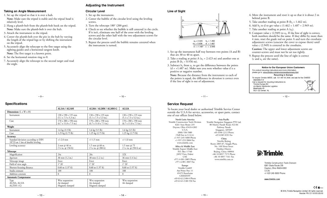
Line of Sight
a2 |
| b2 |
a1 |
| b1 |
|
| B |
A |
|
|
a2 = 2.423 | b2 = 1.462 | |
+b1 = 0.936 | = 1.487 | |
d = +1.487 | c | = 2.949 |
1.Set up the instrument half way between two points (A and B) that are 30 to 40 m apart.
2.Take a reading at point A (a1 = 2.423 m) and another one at point B (b1 = 0.936 m).
3.Subtract b1 from a1 to get the difference between the points (d = +1.487 m). Make sure you note whether value d is a positive or negative number.
Note: Because the distance from the instrument to each of the points is equal, the difference in elevation is correct even if the line of sight is out of adjustment.
4.Move the instrument and reset it up so that it is about 2 m behind point B.
5.Take another reading at point B (b2 = 1.462 m).
6.Add b2 to d to get value c (1.462 + 1.487 = 2.949 m).
7.Take another reading at point A (a2).
8.Compare value c (2.949) to a2. If the line of sight is correct, both numbers should be the same. If they differ by more than
4 mm, reset the grade rod on point A and turn the crosshairs adjustment screws (unscrew the cover to expose them) until value c (2.949) is centered in the crosshairs.
Caution: The upper and lower adjustment screws are
9.Repeat the process until the line of sight is correct (c and a2 are the same).
Notice to Our European Union Customers
For product recycling instructions and more information, please go to: www.trimble.com/environment/summary.html
Recycling in Europe
To recycle Trimble WEEE, call: +31 497 53 2430, and ask for the ÒWEEE associate,Ó or
mail a request for recycling instructions to: Trimble Europe BV
c/o Menlo Worldwide Logistics Meerheide 45
5521 DZ Eersel, NL
– 9 – | – 10 – |
Specifications
| AL24A / AL24M | AL28A / AL28M / | AL32A |
Dimensions (L x W x H) |
|
|
|
Instrument | 130 x 190 x 135 mm | 130 x 190 x 135 mm | 130 x 190 x 135 mm |
| (5.1 x 7.5 x 5.3 in.) | (5.1 x 7.5 x 5.3 in.) | (5.1 x 7.5 x 5.3 in.) |
Case | 170 x 280 x 190 mm | 170 x 280 x 190 mm | 170 x 280 x 190 mm |
| (6.7 x 11.0 x 7.5 in.) | (6.7 x 11.0 x 7.5 in.) | (6.7 x 11.0 x 7.5 in.) |
Weight |
|
|
|
Instrument | 1.6 kg (3.5 lb) | 1.6 kg (3.5 lb) | 1.6 kg (3.5 lb) |
Case | 1.25 kg (2.75 lb) | 1.25 kg (2.75 lb) | 1.25 kg (2.75 lb) |
Accuracy |
|
|
|
Standard deviation according to DIN | |||
18723 on 1 km of double leveling |
|
|
|
Leveling accuracy | 3 mm @ 46 m | 1.5 mm @ 60 m | 1.5 mm @ 75 |
| (1/8 in. @ 150 ft) | (1/16 in. @ 200 ft) | (1/16 in. @ 250 ft m) |
Telescope |
|
|
|
Magnification | 24x | 28x | 32X |
Aperture | 30 mm (1.2 in.) | 30 mm (1.2 in.) | 36 mm (1.4 in.) |
Telescope image | Erect | Erect | Erect |
Field of view angle | 1° 20' | 1° 20' | 1° 20' |
Shortest focusing distance | 0.60 m (1.97 ft) | 0.60 m (1.97 ft) | 0.60 m (1.97 ft) |
Stadia constant | 100 | 100 | 100 |
Addition constant | 0 | 0 | 0 |
Automatic Compensator |
|
|
|
Type | Wire suspension: | Wire suspension: | Wire suspension: |
AL2XA, AL32A | Air damped | Air damped | Air damped |
AL2XM | Magnetic damped | Magnetic damped |
|
– 13 – |
|
| – 14 – |
– 11 –
Service Request
To locate your local dealer or authorized Trimble Service Center
outside the U.S.A for service, accessories, or spare parts, contact
one of our offices listed below.
|
| |
Trimble Construction Tools Division | Trimble Navigation Singapore PTE Ltd. | |
8261 State Route 235 | 80 Marine Parade Road, | |
Dayton, Ohio | Parkway Parade | |
U.S.A. | Singapore, 449269 | |
(800) | +65 6348 2212 Phone | |
(Toll Free in U.S.A.) | +65 6348 2232 Fax | |
China | ||
Trimble Beijing | ||
www.trimble.com | ||
Room | ||
| ||
Africa & Middle East | No. 168 Xiwai Street | |
Trimble Export | Haidian District | |
P.O. Box 17760 | Beijing, China 100044 | |
JAFZ View, Dubai | +86 10 8857 7575 Phone | |
UAE | +86 10 8857 7161 Fax | |
www.trimble.com.cn | ||
| ||
Europe |
| |
Trimble GmbH |
| |
Am Prime Parc 11 |
| |
65479 Raunheim |
| |
GERMANY |
| |
| ||
|
– 15 –
– 12 –
Trimble Construction Tools Division
8261 State Route 235
Dayton, Ohio
U.S.A.
www.trimble.com
![]() N324
N324
© 2010, Trimble Navigation Limited. All rights reserved. Reorder PN