160 specifications
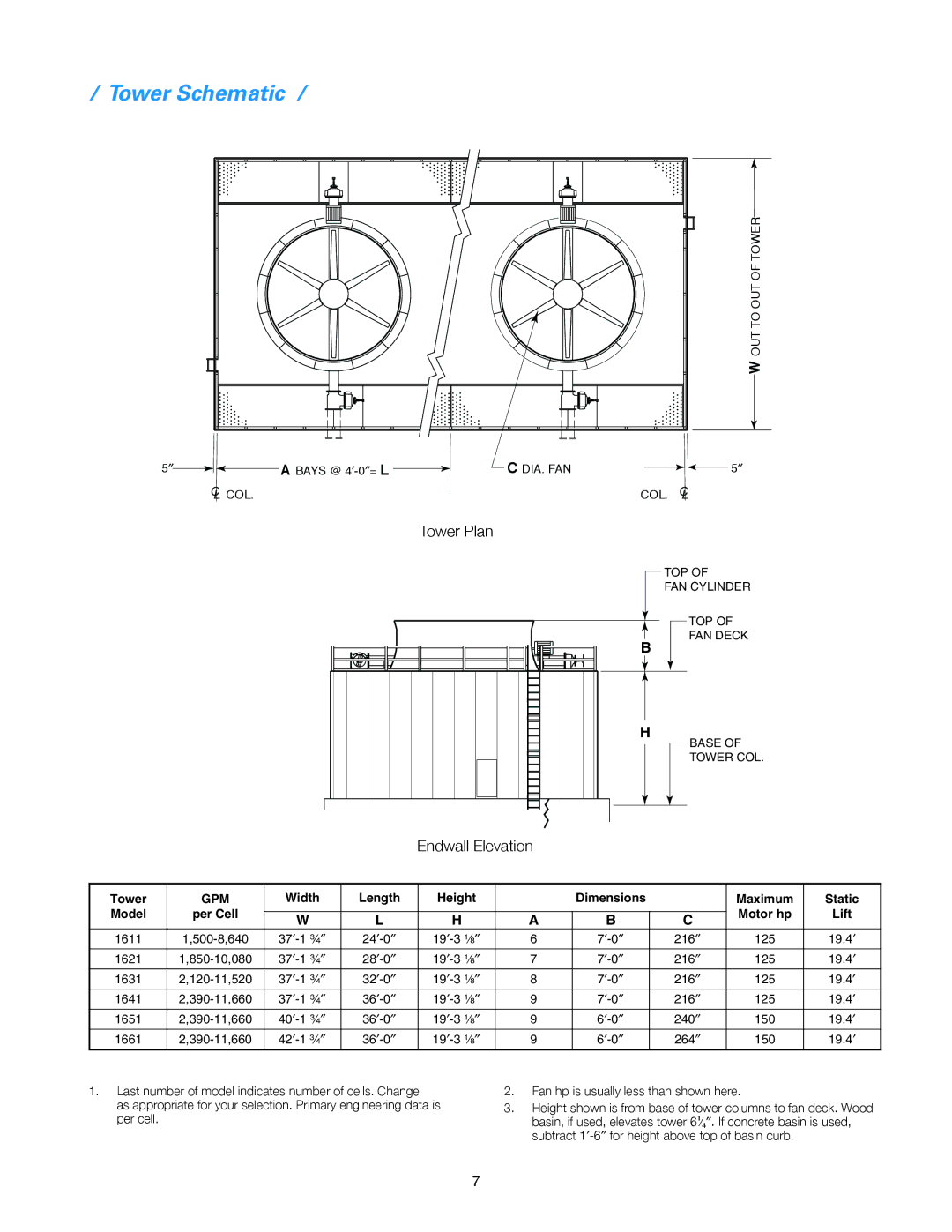
SPX Cooling Technologies 160 is a prominent cooling tower option designed for a range of industrial and commercial applications. This advanced system reflects a commitment to efficiency, performance, and adaptability, making it a leading choice for organizations looking to optimize their cooling processes.One of the standout features of the SPX Cooling Technologies 160 is its modular design. This allows for flexibility in installation and scalability based on specific cooling requirements. Whether you need a single unit or multiple towers, the modularity ensures that the system can be configured to meet the unique demands of various projects.
The cooling tower employs advanced materials that enhance durability and resistance to corrosion, extending the lifespan of the system. This is crucial for industrial environments where exposure to harsh conditions is common. The design focuses on energy efficiency as well, incorporating fan and motor technology that reduces power consumption while maximizing airflow and cooling performance.
Another significant characteristic of the SPX 160 is its advanced thermal performance. With a well-designed heat transfer surface, the cooling tower operates efficiently, ensuring optimal heat exchange between the water and the air. This process effectively reduces water temperatures, leading to significant energy savings and improved operational efficiency.
The unit is equipped with state-of-the-art controls that enhance its functionality. These smart control systems allow for precise regulation of cooling operations, optimizing performance based on real-time needs. This not only boosts efficiency but also supports maintenance schedules, aiding in the longevity of the equipment.
Furthermore, the SPX Cooling Technologies 160 is designed with environmental considerations in mind. It features low-noise operation, which is essential for installations in noise-sensitive areas. Additionally, the cooling tower can be customized with options that minimize water usage, aligning with sustainability goals many organizations prioritize today.
Overall, the SPX Cooling Technologies 160 stands out in the market for its combination of adaptability, efficiency, and innovation. Its design and features make it a compelling solution for businesses in need of reliable cooling solutions, ultimately contributing to improved operational performance and sustainability. Whether for industrial plants, commercial buildings, or unique applications, the SPX 160 is a credible option in the cooling technology landscape.

