DESCRIPTION OF FUNCTIONS
on a channel the mixer is close to clip- ping (distorting) the audio signal and the gains should be turned down.
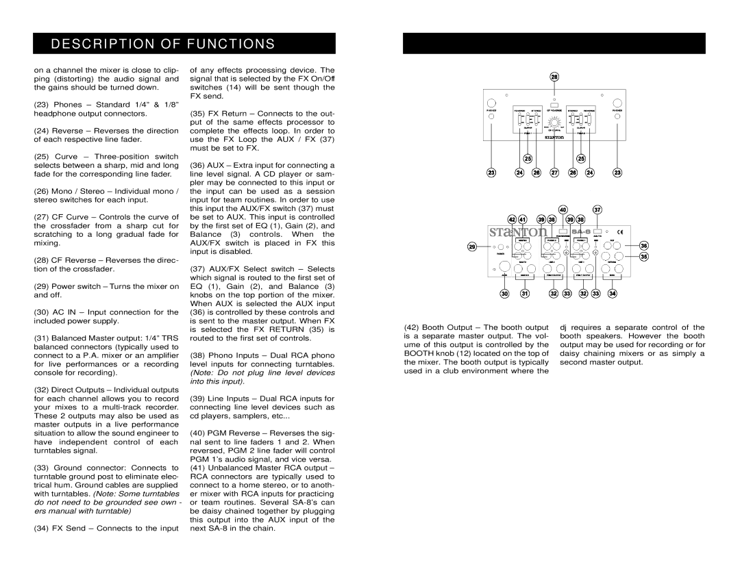
(23)Phones – Standard 1/4” & 1/8” headphone output connectors.
(24)Reverse – Reverses the direction of each respective line fader.
(25)Curve –
(26)Mono / Stereo – Individual mono / stereo switches for each input.
(27)CF Curve – Controls the curve of the crossfader from a sharp cut for scratching to a long gradual fade for mixing.
(28)CF Reverse – Reverses the direc- tion of the crossfader.
(29)Power switch – Turns the mixer on and off.
(30)AC IN – Input connection for the included power supply.
(31)Balanced Master output: 1/4” TRS balanced connectors (typically used to connect to a P.A. mixer or an amplifier for live performances or a recording console for recording).
(32)Direct Outputs – Individual outputs for each channel allows you to record your mixes to a
(33)Ground connector: Connects to turntable ground post to eliminate elec- trical hum. Ground cables are supplied with turntables. (Note: Some turntables do not need to be grounded see own - ers manual with turntable)
(34)FX Send – Connects to the input
of any effects processing device. The signal that is selected by the FX On/Off switches (14) will be sent though the FX send.
(35)FX Return – Connects to the out- put of the same effects processor to complete the effects loop. In order to use the FX Loop the AUX / FX (37) must be set to FX.
(36)AUX – Extra input for connecting a line level signal. A CD player or sam- pler may be connected to this input or the input can be used as a session input for team routines. In order to use this input the AUX/FX switch (37) must be set to AUX. This input is controlled by the first set of EQ (1), Gain (2), and Balance (3) controls. When the AUX/FX switch is placed in FX this input is disabled.
(37)AUX/FX Select switch – Selects which signal is routed to the first set of EQ (1), Gain (2), and Balance (3) knobs on the top portion of the mixer. When AUX is selected the AUX input
(36)is controlled by these controls and is sent to the master output. When FX is selected the FX RETURN (35) is routed to the first set of controls.
(38)Phono Inputs – Dual RCA phono level inputs for connecting turntables. (Note: Do not plug line level devices into this input).
(39)Line Inputs – Dual RCA inputs for connecting line level devices such as cd players, samplers, etc...
(40)PGM Reverse – Reverses the sig- nal sent to line faders 1 and 2. When reversed, PGM 2 line fader will control PGM 1’s audio signal, and vice versa.
(41)Unbalanced Master RCA output – RCA connectors are typically used to connect to a home stereo, or to anoth- er mixer with RCA inputs for practicing or team routines. Several
(42)Booth Output – The booth output is a separate master output. The vol- ume of this output is controlled by the BOOTH knob (12) located on the top of the mixer. The booth output is typically used in a club environment where the
dj requires a separate control of the booth speakers. However the booth output may be used for recording or for daisy chaining mixers or as simply a second master output.
