CAUTION: Do not "high pin" and/or "double pin" a weight stack. This action is con- sidered to be dangerous to users, and bystanders, and may damage your INSTINCT SHOULDER PRESS. Aside from the mechanical damage that may result, such action(s), in part, may cause the weight stack to crush or pinch fingers, hands and/or extremities. DO NOT use the unit if the top plate is elevated and/or pinned in a raised position. Seek assistance from authorized personnel to correct such a condition.
PREVENTIVE MAINTENANCE
MAINTENANCE SCHEDULE
Star Trac strongly recommends performing regular preventive maintenance on your STAR TRAC INSTINCT SHOULDER PRESS. Without regularly scheduled maintenance, normal wear and tear may cause cumulative effects, such as misalignment or premature wear, resulting in downtime. For this reason, we highly recommend following the maintenance schedules. Additionally, unusual symptoms, such as excessive noise during use, stiffness or free play in moving parts, etc., should be investigated and nec- essary corrective actions (adjustment or parts replacement) should be performed. If any components are found to be worn or dam- aged, the unit should be removed from service until repairs can be made. Only components supplied or approved by Star Trac shall be used to maintain and/or repair the unit.
DAILY MAINTENANCE
■Wipe down and inspect the framework and other structural components (see FRAMEWORK MAINTENANCE on page 13 for requirements). Check all attaching hardware for security. Tighten as needed.
■Clean and inspect the upholstered cushions and the hand grips (see UPHOLSTERY MAINTENANCE on page 13 for require- ments).
■Clean and lubricate guide rods using a cotton cloth and
■Inspect weight belt for excessive wear or other damage. Check weight belt for proper tension (weight belt deflection at any point should not exceed 25 mm); adjust as needed. (See WEIGHT / BELT INSPECTION REQUIREMENTS on page 14 for requirements.)
■Check leverage arm for evidence of sticking or binding; lubricate as needed bearings are equipped with fitting to facilitate lubrication).
While holding the free end of the belt, press down on the opposite side of the belt so it lays flat against the inside of the clamp.
Insert the belt retainer (32) into the belt clamp. BE SURE the tapped hole in the belt retainer is aligned with the mating hole in the belt clamp.
CAUTION: BE SURE to keep the weight belt straight when installing the retaining screw (43) in the belt retainer (32). Misalignment of the weight belt may bias the top plate, which can cause excessive contact of the top plate shaft with the weights, resulting in excessive noise during use, and potential hazards to the user or other bystanders.
Thread the retaining screw (43) through the belt clamp and into the belt retainer (32). Tighten the retaining screw to 400
Route the weight belt (33) over six pulleys, as illustrated.
Insert the free end of the weight belt (33) through the slot in the leverage arm belt clamp, and pull through the opposite slot just until force is applied against the top plate (10). This will eliminate any slack in the belt and ensure proper ten- sioning.
While maintaining tension on the weight belt, press down on the free end of the belt so it lays flat against the inside of the belt clamp.
Insert the belt retainer (32) into the belt clamp. BE SURE the tapped hole in the belt retainer is aligned with the mating hole in the belt clamp.
Thread the retaining screw (43) through the belt clamp and into the belt retainer (32). Tighten the retaining screw to 400
Check for proper tensioning of the weight belt by applying lateral pressure to the belt at a point midway between two pul- leys. Deflection of the weight belt should be less than 25 mm. Loosen the retaining screw (43) and adjust belt tension as needed.
1
4
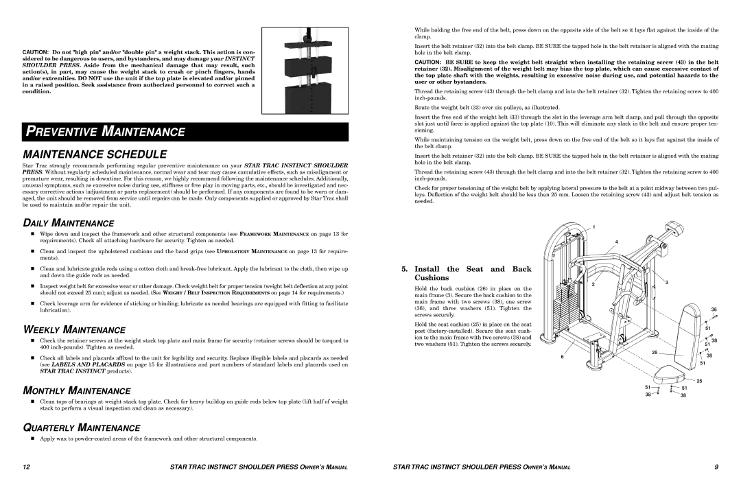
5.Install the Seat and Back Cushions
| 2 | 3 |
Hold the back cushion (26) in place on the |
| |
|
| |
main frame (3). Secure the back cushion to the |
|
|
main frame with two screws (38), one screw |
|
|
(36), and three washers (51). Tighten the |
| 36 |
screws securely. |
|
|
WEEKLY MAINTENANCE
■Check the retainer screws at the weight stack top plate and main frame for security (retainer screws should be torqued to 400
■Check all labels and placards affixed to the unit for legibility and security. Replace illegible labels and placards as needed (see LABELS AND PLACARDS on page 15 for illustrations and part numbers of standard labels and placards used on STAR TRAC INSTINCT products).
MONTHLY MAINTENANCE
■Clean tops of bearings at weight stack top plate. Check for heavy buildup on guide rods below top plate (lift half of weight stack to perform a visual inspection and clean as necessary).
QUARTERLY MAINTENANCE
■Apply wax to
Hold the seat cushion (25) in place on the seat post
51
38
| 51 |
6 | 26 |
38 | |
| 51 |
| 25 |
51 | 51 |
38 | 38 |
12 | STAR TRAC INSTINCT SHOULDER PRESS OWNER’S MANUAL | STAR TRAC INSTINCT SHOULDER PRESS OWNER’S MANUAL | 9 |