WEIGHT BELT INSPECTION REQUIREMENTS
WARNING: REPLACE WORN WEIGHT BELTS IMMEDIATELY. FAILURE TO COMPLY CAN RESULT IN HAZ- ARDOUS CONDITIONS FOR USERS OR OTHER BYSTANDERS.
Inspect all weight belts for evidence of excessive wear or other damage. Give particular attention to the following conditions:
■ Torn or cracked belt
■ Exposed belt cords
■ Worn edges
ASSEMBLY
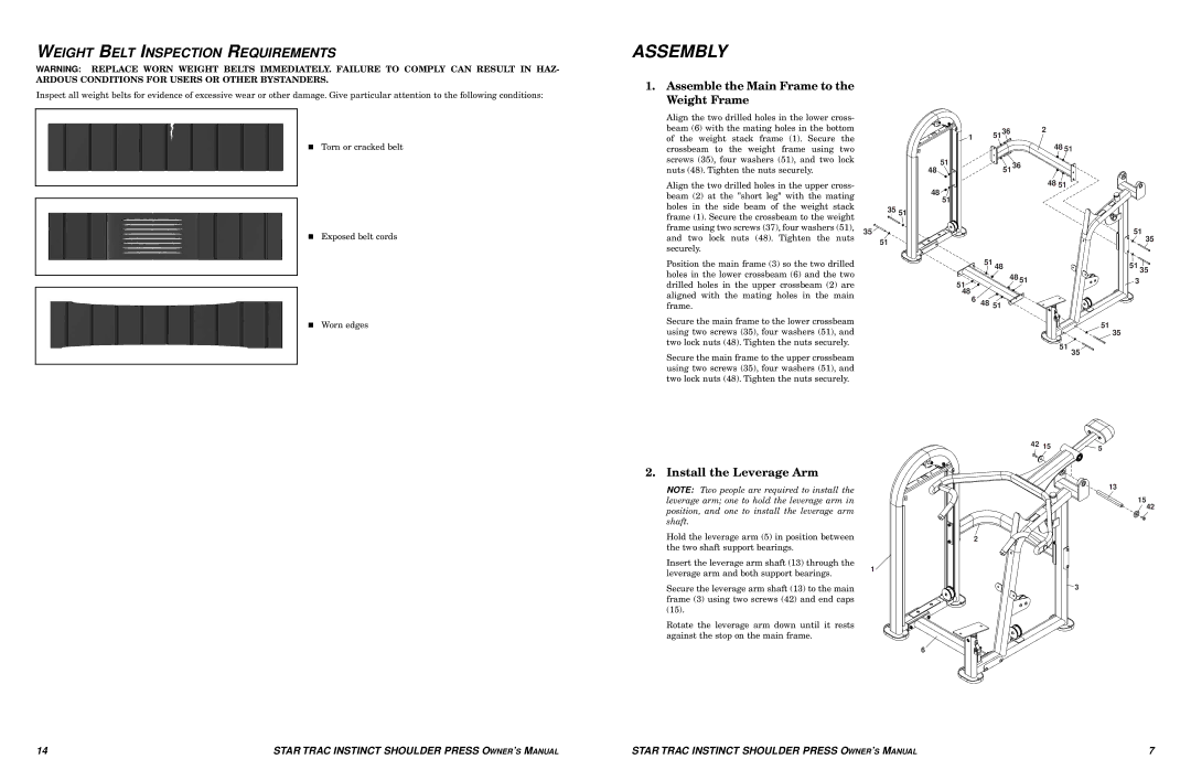
1.Assemble the Main Frame to the Weight Frame
Align the two drilled holes in the lower cross- |
|
|
|
|
|
beam (6) with the mating holes in the bottom |
| 1 | 5136 | 2 |
|
of the weight stack frame (1). Secure the |
| 48 51 |
| ||
crossbeam to the weight frame using two |
|
|
|
| |
screws (35), four washers (51), and two lock |
| 51 | 51 36 |
|
|
nuts (48). Tighten the nuts securely. |
| 48 |
|
| |
Align the two drilled holes in the upper cross- |
| 48 |
| 48 51 |
|
beam (2) at the "short leg" with the mating |
|
|
|
| |
| 51 |
|
|
| |
holes in the side beam of the weight stack |
|
|
|
| |
35 | 51 |
|
|
| |
frame (1). Secure the crossbeam to the weight |
|
|
| ||
|
|
|
|
| |
frame using two screws (37), four washers (51), 35 |
|
|
| 51 | |
and two lock nuts (48). Tighten the nuts | 51 |
|
|
| 35 |
securely. |
|
|
|
| |
|
|
|
|
| |
Position the main frame (3) so the two drilled |
|
| 51 48 | 51 | 35 |
holes in the lower crossbeam (6) and the two |
|
| 48 51 |
| |
|
| 3 |
| ||
drilled holes in the upper crossbeam (2) are |
| 51 |
| ||
aligned with the mating holes in the main |
| 48 |
|
|
|
| 6 | 48 51 |
|
| |
frame. |
|
|
| ||
Secure the main frame to the lower crossbeam |
|
|
| 51 |
|
using two screws (35), four washers (51), and |
|
|
|
| |
|
|
| 35 |
| |
two lock nuts (48). Tighten the nuts securely. | 51 |
|
Secure the main frame to the upper crossbeam | 35 | |
|
|
using two screws (35), four washers (51), and two lock nuts (48). Tighten the nuts securely.
42 155
2. Install the Leverage Arm
NOTE: Two people are required to install the | 13 | |
| ||
leverage arm; one to hold the leverage arm in | 15 | |
position, and one to install the leverage arm | 42 | |
| ||
shaft. |
| |
Hold the leverage arm (5) in position between | 2 | |
the two shaft support bearings. |
| |
Insert the leverage arm shaft (13) through the | 1 | |
leverage arm and both support bearings. | ||
| ||
Secure the leverage arm shaft (13) to the main | 3 | |
frame (3) using two screws (42) and end caps |
| |
(15). |
|
Rotate the leverage arm down until it rests against the stop on the main frame.
6
14 | STAR TRAC INSTINCT SHOULDER PRESS OWNER’S MANUAL | STAR TRAC INSTINCT SHOULDER PRESS OWNER’S MANUAL | 7 |