6 in. (15 cm)


MIN. LENGTH


ATTACH 45°


SEALANT


TERMINATION


ELBOW


VENT PIPING TO BE


RODENT


SLOPED (DOWN)


TOWARD HEATER


SCREEN


TO PREVENT WATER


(INSTALL


12 in.

INTO


FROM COLLECTING.

SEALANT

(30 cm) min.

ELBOW)


GROUND


LEVEL*

*WHERE SNOW COVER IS NORMALDURING WINTER, ENSURE SUFFICIENT VENT CLEARANCE TO PREVENT BLOCKAGE OR ICE BUILDUP.

FIGURE 25

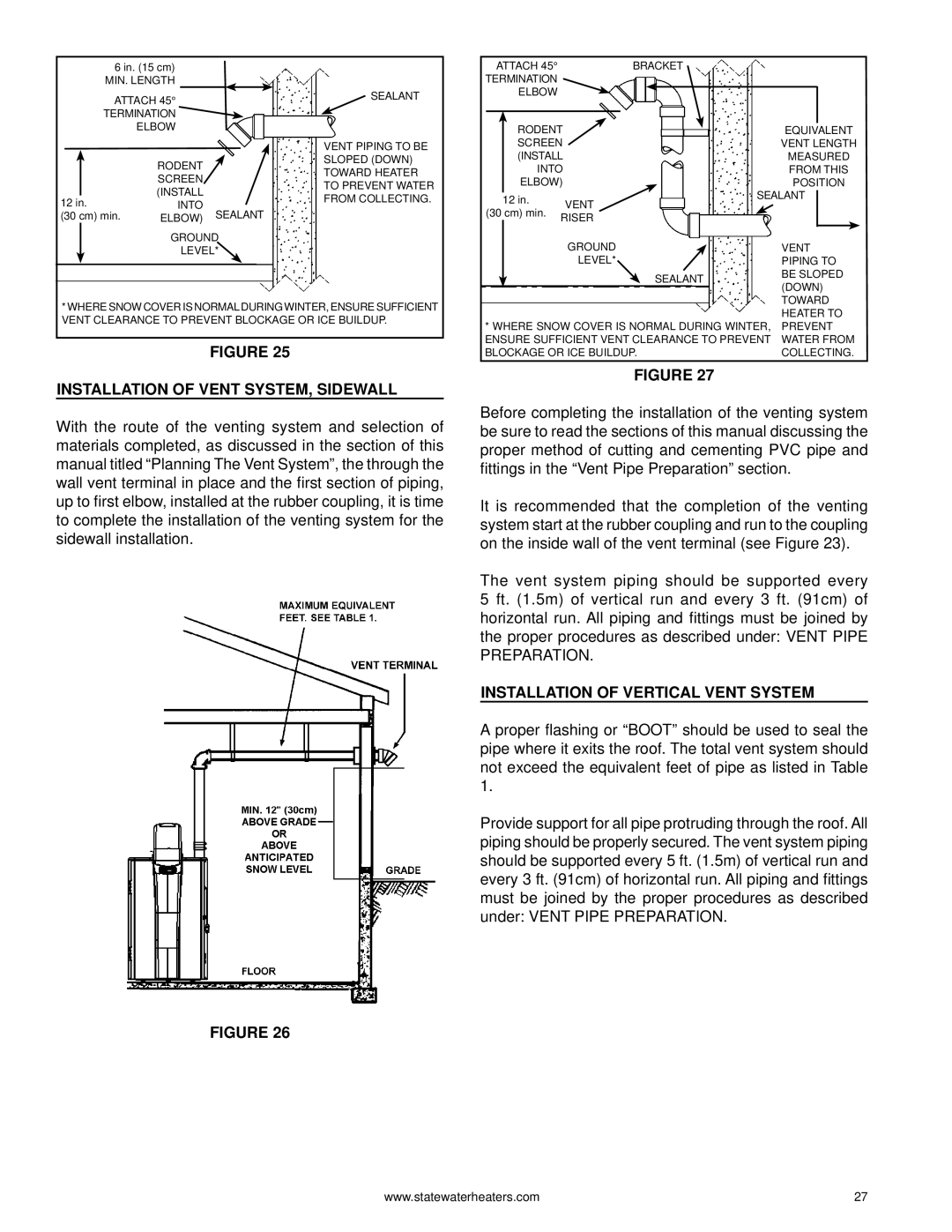
INSTALLATION OF VENT SYSTEM, SIDEWALL

With the route of the venting system and selection of materials completed, as discussed in the section of this manual titled “Planning The Vent System”, the through the wall vent terminal in place and the first section of piping, up to first elbow, installed at the rubber coupling, it is time to complete the installation of the venting system for the sidewall installation.

FIGURE 26


ATTACH 45°


BRACKET


TERMINATION


ELBOW


RODENT


EQUIVALENT


SCREEN


VENT LENGTH


(INSTALL


MEASURED


INTO


FROM THIS


ELBOW)


POSITION


SEALANT


12 in.


VENT

(30 cm) min.


RISER


GROUND


VENT


LEVEL*


PIPING TO


SEALANT

BE SLOPED


(DOWN)


TOWARD

* WHERE SNOW COVER IS NORMAL DURING WINTER,

HEATER TO

PREVENT

ENSURE SUFFICIENT VENT CLEARANCE TO PREVENT

WATER FROM

BLOCKAGE OR ICE BUILDUP.

COLLECTING.

FIGURE 27

Before completing the installation of the venting system be sure to read the sections of this manual discussing the proper method of cutting and cementing PVC pipe and fittings in the “Vent Pipe Preparation” section.

It is recommended that the completion of the venting system start at the rubber coupling and run to the coupling on the inside wall of the vent terminal (see Figure 23).

The vent system piping should be supported every 5 ft. (1.5m) of vertical run and every 3 ft. (91cm) of horizontal run. All piping and fittings must be joined by the proper procedures as described under: VENT PIPE PREPARATION.

INSTALLATION OF VERTICAL VENT SYSTEM

A proper flashing or “BOOT” should be used to seal the pipe where it exits the roof. The total vent system should not exceed the equivalent feet of pipe as listed in Table 1.

Provide support for all pipe protruding through the roof. All piping should be properly secured. The vent system piping should be supported every 5 ft. (1.5m) of vertical run and every 3 ft. (91cm) of horizontal run. All piping and fittings must be joined by the proper procedures as described under: VENT PIPE PREPARATION.

www.statewaterheaters.com

27

Page 27
Image 27
State Industries GPH-90N, 0710 316888-002 Installation of Vent SYSTEM, Sidewall, Installation of Vertical Vent System

0710 316888-002, GPH-90N specifications

The State Industries GPH-90N,0710 316888-002 is a high-quality water heater designed to meet the demands of both residential and commercial applications. Renowned for its durability and efficiency, this model serves as an essential component for facilities requiring reliable hot water supply.

One of the standout features of the GPH-90N is its impressive heating capacity, which allows it to deliver hot water quickly and effectively. This model boasts a heating input of 90,000 BTU per hour, making it suitable for large households or commercial establishments. The unit is designed to maintain consistent water temperatures, ensuring that users have access to hot water whenever needed.

The GPH-90N is also equipped with advanced technologies that enhance its operational efficiency. It features a modulating gas burner that adjusts its output to match the flow rate of hot water demanded, thereby optimizing energy use and minimizing operating costs. This technology not only improves performance but also extends the lifespan of the water heater.

Durability is a key characteristic of the State Industries GPH-90N. The unit is crafted from high-quality materials, including a robust stainless steel tank that resists corrosion and ensures long-lasting performance. This corrosion-resistant design is particularly beneficial in areas with hard water, where mineral deposits can be a significant concern. Additionally, the tank is insulated with high-density foam, which helps to maintain heat and reduce standby heat loss.

A crucial aspect of the GPH-90N is its user-friendly features. The control panel is straightforward, allowing users to adjust settings with ease. The water heater is also designed for simple maintenance, ensuring that annual servicing can be carried out with minimal disruption.

Safety is paramount in the design of the GPH-90N. It includes multiple safety features, such as a pressure relief valve and a safety shut-off mechanism, which provide peace of mind for users. This ensures that the unit operates safely under varying conditions.

In conclusion, the State Industries GPH-90N,0710 316888-002 is a powerful and efficient water heater that combines advanced technology with durable construction. Its high heating capacity and user-friendly design make it a reliable choice for both residential and commercial applications, ensuring that hot water is always available when needed.