A gas line of sufficient size must be run to the water heater. Consult the current edition of National Fuel Gas Code (ANSI Z223.1/NFPA
54)or the Natural Gas and Propane Installation Code (CAN/CSA B149.1) and your gas supplier concerning pipe size.
There must be:
•A readily accessible manual shut off valve in the gas supply line serving the water heater, and
•A drip leg (sediment trap) ahead of gas control valve to help prevent dirt and foreign materials from entering the gas control valve.
•A flexible gas connector or a ground joint union between the shut off valve and control valve to permit servicing of the unit.
Be sure to check all the gas piping for leaks before lighting the water heater. Use a soapy water solution, not a match or open flame. Rinse off soapy solution and wipe dry.
Use pipe joint compound or teflon tape marked as being resistant to the action of petroleum [Propane (L.P.)] gases.
The appliance and its gas connection must be leak tested before placing the appliance in operation.
The appliance and its individual
system at test pressures in excess of 1/2 pound per square inch (3.5 kPa). It should be isolated from the gas supply piping system by closing
its individual manual
per square inch (3.5 kPa).
Connecting gas piping to the gas control valve of water heater can be accomplished by either of two methods shown in Figures 12 and 13.
SEDIMENT TRAPS
A sediment trap should be installed as close to the inlet of the water heater as practical at the time of water heater installation. The sediment trap should be either a tee fitting with a capped nipple in the bottom outlet or other device recognized as an effective sediment trap. If a tee fitting is used, it should be installed in conformance with one of the methods of installation shown in Figures 12 and 13.
Contaminants in the gas lines may cause improper operation of the gas control valve that may result in fire or explosion. Before attaching the gas line be sure that all gas pipe is clean on the inside. To trap any dirt or foreign material in the gas supply line, a drip leg (sometimes called a sediment trap) must be incorporated in the piping. The drip leg must be readily accessible. Install in accordance with the “Gas Piping” section. Refer to the current edition of the National Fuel Gas Code (ANSI Z223.1/NFPA 54) or the Natural Gas and Propane Installation Code (CAN/CSA B149.1).
FIGURE 12. GAS PIPING WITH
FLEXIBLE CONNECTOR.
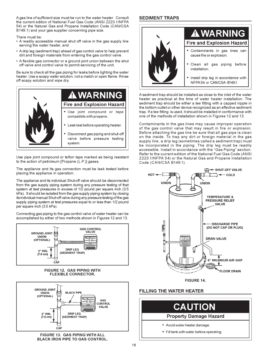
FIGURE 14.
Filling the Water Heater
FIGURE 13. GAS PIPING WITH ALL
BLACK IRON PIPE TO GAS CONTROL.
18