State Industries SUF 60 THRU 120, SUF 130 THRU 500, SUF 100 THRU 250 manual Direct Vent

Models: SUF 100 THRU 250 SUF 130 THRU 500 SUF 60 THRU 120

1 49
Download 49 pages 27.36 Kb
Page 17
Image 17

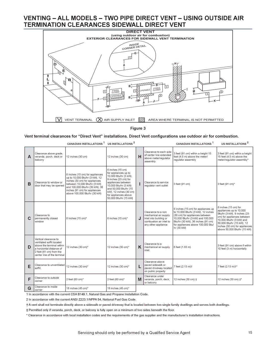
VENTING – ALL MODELS – TWO PIPE DIRECT VENT – USING OUTSIDE AIR TERMINATION CLEARANCES SIDEWALL DIRECT VENT


DIRECT VENT


(using outdoor air for combustion)


EXTERIOR CLEARANCES FOR SIDEWALL VENT TERMINATION


G


V


D


A


H


v E


L

B


v


B


B


C


V


FIXED


E


V

FIXED


V


OPERABL

CLOSED


M


X


CLOSED


V


OPERABL

E


X


V

B


V


F


B


J


K


A


B


V

VENT TERMINAL

X AIR SUPPLY INLET


AREA WHERE TERMINAL IS NOT PERMITTED

Figure 3

Vent terminal clearances for “Direct Vent” installations. Direct Vent configurations use outdoor air for combustion.


CANADIAN INSTALLATIONS 1

US INSTALLATIONS 2


CANADIAN INSTALLATIONS 1

US INSTALLATIONS 2


Clearance above grade,


Clearance to each side

3 feet (91 cm) within a height 15

3 feet (91 cm) within a height

A


H

of center line extended

veranda, porch, deck or

12 inches (30 cm)

12 inches (30 cm)

above meter/regulator

feet (4.5 m) above the meter/

15 feet (4.5 m) above the


balcony


assembly

regulator assembly

meter/regulator assembly*


6 inches (15 cm)


6 inches (15 cm) for appliances

for appliances up to


10,000 Btu/hr (3 kW),


up to 10,000 Btu/hr (3 kW), 12


9 inches (23 cm) for


inches (30 cm) for appliances


B

Clearance to window or

appliances between

I

Clearance to service


between 10,000 Btu/hr (3 kW)

3 feet (91 cm)

3 feet (91 cm)*

door that may be opened

10,000 Btu/hr (3 kW)

regulator vent outlet


and 100,000 Btu/hr (30 kW), 36

and 50,000 Btu/hr (15


inches (91 cm) for appliances


kW), 12 inches (30 cm)


above 100,000 Btu/hr (30 kW)


for appliances above


50,000 Btu/hr (15 kW)


6 inches (15 cm) for appliances up

6 inches (15 cm) for


appliances up to 10,000


Clearance to a non

to 10,000 Btu/hr (3 kW), 12 inches


Btu/hr (3 kW), 9 inches (23


Clearance to


mechanical air supply

(30 cm) for appliances between

C


J

cm) for appliances between

permanently closed

6 inches (15 cm)*

6 inches (15 cm)*

inlet into building or

10,000 Btu/hr (3 kW) and 100,000

10,000 Btu/hr (3 kW) and


window


combustion air inlet to

Btu/hr (30 kW), 36 inches (91 cm)

50,000 Btu/hr (15 kW), 12


any other appliance

for appliances above 100,000 Btu/


inches (30 cm) for appliances


hr (30 kW)


above 50,000 Btu/hr (15 kW)


Vertical clearance to


ventilated soffit located


Clearance to a


D

above the terminal within


K


3 feet (91 cm) above if within

12 inches (30 cm)*

12 inches (30 cm)*

mechanical air supply

6 feet (1.83 m)

a horizontal distance of

10 feet (3 m) horizontally


2 feet (61 cm) from the


inlet


center line of the terminal


Clearance above


E

Clearance to unventilated

12 inches (30 cm)*

12 inches (30 cm)*

L

paved sidewalk or

7 feet (2.13 m)†

7 feet (2.13 m)†*

soffit

paved driveway located


on public property


F

cornerClearance to outside


M

Clearance under


2 feet (60 cm)*

2 feet (60 cm)*

veranda, porch, deck,

12 inches (30 cm) ‡

12 inches (30 cm) ‡*


or balcony


G

cornerClearance to inside

18 inches (45 cm)*

18 inches (45 cm)*


1 In accordance with the current CSA B149.1, Natural Gas and Propane Installation Code. 2 In accordance with the current ANSI Z223.1/NFPA 54, National Fuel Gas Code.

A vent shall not terminate directly above a sidewalk or paved driveway that is located between two single family dwellings and serves both dwellings.

‡ Permitted only if veranda, porch, deck, or balcony is fully open on a minimum of two sides beneath the floor.

* Clearance in accordance with local installation codes and the requirements of the gas supplier and the manufacturer’s installation instructions.

Servicing should only be performed by a Qualified Service Agent

15

Page 17
Image 17
State Industries SUF 60 THRU 120, SUF 130 THRU 500, SUF 100 THRU 250 manual Direct Vent

SUF 100 THRU 250, SUF 130 THRU 500, SUF 60 THRU 120 specifications

State Industries has long been a leader in the manufacturing of high-quality water heaters, particularly known for its SUF series. The SUF 60 thru 120, SUF 130 thru 500, and SUF 100 thru 250 models are excellent examples of State Industries’ commitment to efficiency, performance, and innovation. These units are designed to meet a range of residential and commercial water heating needs, showcasing advanced engineering and durability.

The SUF series is primarily built for heavy-duty applications, offering various capacities to accommodate different demands. The SUF 60 thru 120 models are ideal for residential settings, providing dependable hot water solutions with capacity options ranging from 60 to 120 gallons. These units utilize high-quality insulation to minimize heat loss, resulting in improved efficiency and cost-effectiveness.

Moving to the SUF 130 thru 500 series, these models are tailored for larger commercial applications. With capacities extending up to 500 gallons, they are perfect for industries where high volume and consistent hot water supply are essential. The SUF 130 thru 500 models feature robust heating elements and advanced thermostats for precise temperature control, ensuring the delivery of hot water on demand.

The SUF 100 thru 250 units straddle the line between residential and light commercial applications. With capacities from 100 to 250 gallons, these water heaters are versatile and adaptable to various settings. They integrate cutting-edge technology that enhances safety, such as multi-level safety controls and automatic shut-off systems, ensuring user protection while maximizing performance.

Each SUF model is designed with longevity in mind. The tanks are constructed from high-grade materials that resist corrosion and wear, featuring factory-installed anode rods to enhance the lifespan even further. The energy-efficient design of these water heaters meets or exceeds current energy conservation standards, providing an eco-friendly solution without compromising on output.

In summary, State Industries’ SUF 60 thru 120, SUF 130 thru 500, and SUF 100 thru 250 models exemplify the brand’s dedication to quality and innovation. With various capacities, advanced technologies, and a focus on efficiency and durability, these water heaters cater to diverse needs, ensuring reliable hot water supply for years to come.