Manuals
/
State Industries
/
Household Appliance
/
Water Heater
State Industries
SUF 100 THRU 250, SUF 130 THRU 500, SUF 60 THRU 120 Control Sequence Flow Chart
Models:
SUF 100 THRU 250
SUF 130 THRU 500
SUF 60 THRU 120
1
31
49
49
Download
49 pages
27.36 Kb
28
29
30
31
32
33
34
35
<
>
Specs
Install
Error codes
Control Sequence Flow Chart
Power Vent
Blower Proving Switch
Page 31
Image 31
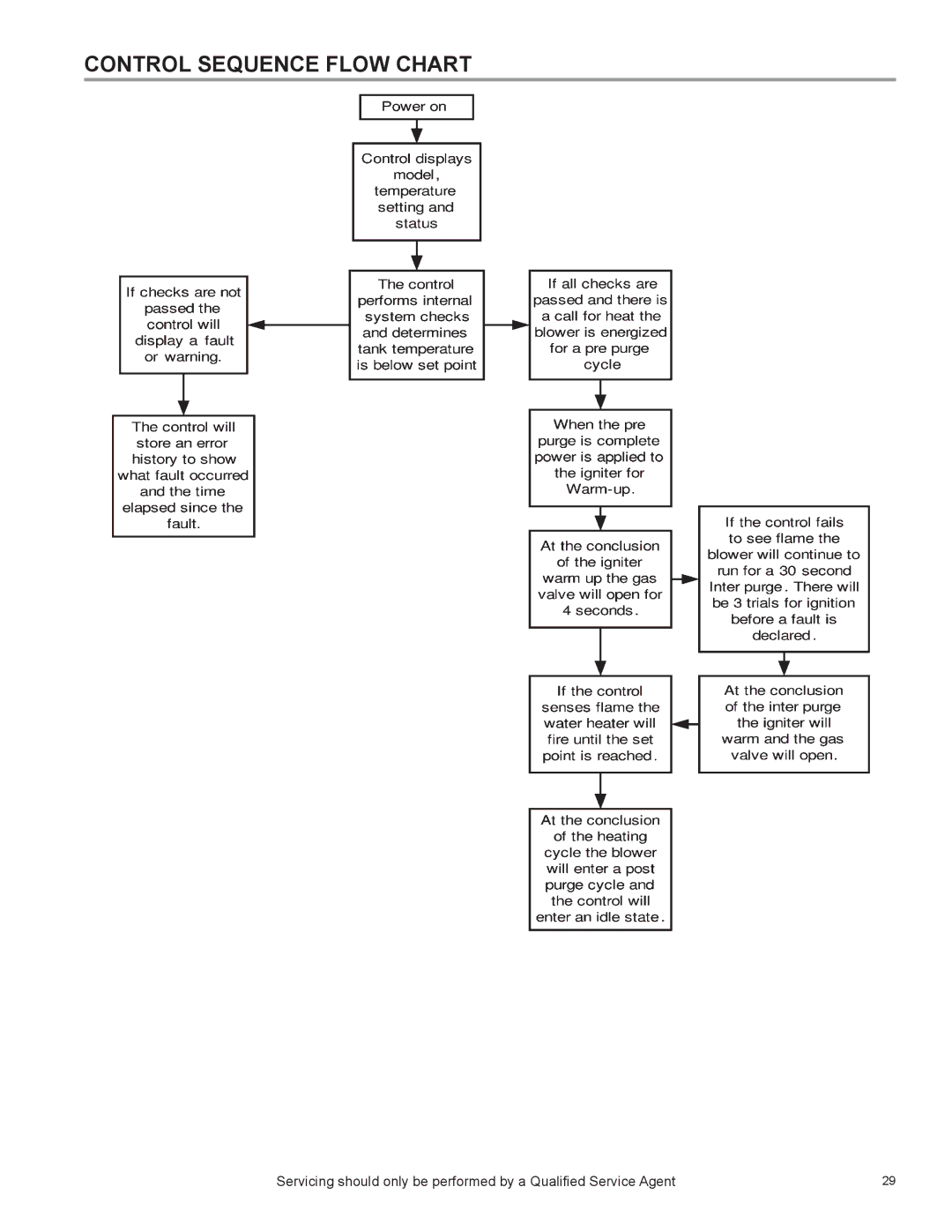
CONTROL SEQUENCE FLOW CHART
Servicing should only be performed by a Qualified Service Agent
29
Page 30
Page 32
Page 31
Image 31
Page 30
Page 32
Contents
Commercial GAS High Efficiency Water Heaters
Page
Table of Contents
Qualifications
Introduction
Tools Required
General Information
GAS Pressure Specifications
Adjustment Procedure GAS Pressure SUF 120 and 150 Models
Installation Quick Tips SUF 120 and 150 GAS Pressure
Page
Important Note
Installation Quick Tips SUF 199 and 250 GAS Pressure
Adjustment Procedure GAS Pressure SUF 300, 400
Installation Quick Tips SUF 300, 400, 500 GAS Pressure
Installation Quick Tips SUF 300, 400
Ultra Force Venting
Installation Venting Category and Materials
Vent Length Table Equivalent Feet Meters 120 through
Venting Tables SUF 120
Vent Length Table Equivalent Feet Meters 300, 400
Concentric Venting
What does the PH Scale MEAN?
Vent Condensation
Can I Drain this Condensation to the Floor DRAIN?
What about the PH Values of Condensate and Soda POP?
Power Vent
Direct Vent
Vent Termination Direct Vent ALL Models
PVC Elbow
Direct Venting ALL Models
Control Overview
Set Point
Status Icon Description
Display
Adjusting Tank Temperature Operating SET Point Differential
Action
Display Action
Press Update to accept the change or Cancel to reset it
Changing the Display Units
Press Update to accept the change or Cancel to reject it
Example of a Warning
Example of a Fault Advanced Diagnostic Information
To get to the current fault information screen, press Menu
Access to the Current Fault or Warning
Press the Down button for more information
Fault Codes
Viewing Information About the Water Heater
Typical Sequence
Control Sequence Typical ALL Models
Control Sequence Flow Chart
Controls Central Control Board CCB
This is the back of the UIM
Controls GAS Valve SUF
Controls GAS Valve SUF
Controls GAS Valve SUF 199
High Altitude Installation
GAS Orifice
Controls GAS Valve SUF 199
Orifice Chart SUF 300
Controls GAS VALVE, Orifice Chart SUF 300/400
Orifice Chart SUF
Controls GAS VALVE, Orifice Chart SUF
Blocked Inlet Proving Switch
Controls Pressure Switches ALL Models
Blower Proving Switch
Blocked Outlet Proving Switch
Controls Pressure Switches SUF 120 Through
Controls Pressure Switches SUF 300, 400
Page
Control Timing
HOT Surface Igniter / Flame Sensor / Control Timing
HOT Surface Igniter
Flame Sensor
Model High Speed Hz Low Speed Hz
Blower Speed Control SUF 199
Variable Frequency Drive SUF 400
Voltage Frequency Speed Instructions VFD Model SUF
Variable Frequency Drive Blower Speed and Pressure Readings
User Interface Modul
Wiring Diagram SUF 120
User Interface Module
Wiring Diagram SUF 400
Tennessee Waltz Parkway Ashland City, TN