ENGLISH | GB |
|
|
SYMBOLS
The following symbols are displayed on the ma- chine in order to remind you about the safety pre- cautions and attention necessary when using the machine.
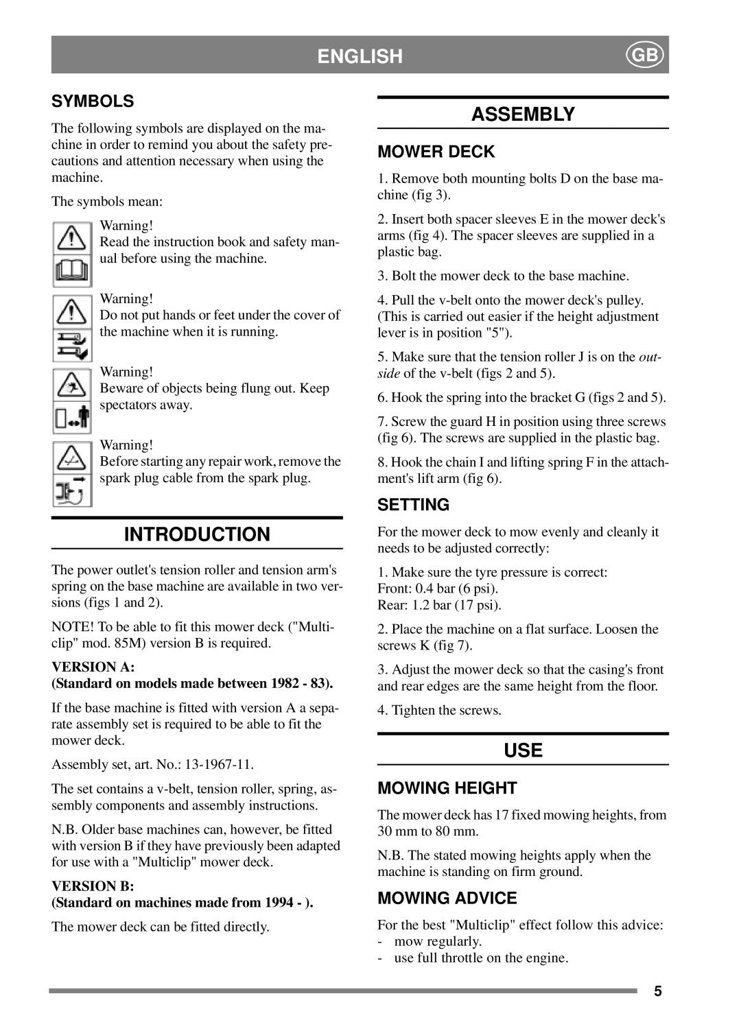
The symbols mean:
Warning!
Read the instruction book and safety man- ual before using the machine.
ASSEMBLY
MOWER DECK
1.Remove both mounting bolts D on the base ma- chine (fig 3).
2.Insert both spacer sleeves E in the mower deck's arms (fig 4). The spacer sleeves are supplied in a plastic bag.
3.Bolt the mower deck to the base machine.
Warning!
Do not put hands or feet under the cover of the machine when it is running.
Warning!
Beware of objects being flung out. Keep spectators away.
Warning!
Before starting any repair work, remove the spark plug cable from the spark plug.
INTRODUCTION
The power outlet's tension roller and tension arm's spring on the base machine are available in two ver- sions (figs 1 and 2).
NOTE! To be able to fit this mower deck ("Multi- clip" mod. 85M) version B is required.
VERSION A:
(Standard on models made between 1982 - 83).
If the base machine is fitted with version A a sepa- rate assembly set is required to be able to fit the mower deck.
Assembly set, art. No.:
The set contains a
N.B. Older base machines can, however, be fitted with version B if they have previously been adapted for use with a "Multiclip" mower deck.
VERSION B:
(Standard on machines made from 1994 - ).
The mower deck can be fitted directly.
4.Pull the
(This is carried out easier if the height adjustment lever is in position "5").
5.Make sure that the tension roller J is on the out- side of the
6.Hook the spring into the bracket G (figs 2 and 5).
7.Screw the guard H in position using three screws (fig 6). The screws are supplied in the plastic bag.
8.Hook the chain I and lifting spring F in the attach- ment's lift arm (fig 6).
SETTING
For the mower deck to mow evenly and cleanly it needs to be adjusted correctly:
1.Make sure the tyre pressure is correct: Front: 0.4 bar (6 psi).
Rear: 1.2 bar (17 psi).
2.Place the machine on a flat surface. Loosen the screws K (fig 7).
3.Adjust the mower deck so that the casing's front and rear edges are the same height from the floor.
4.Tighten the screws.
USE
MOWING HEIGHT
The mower deck has 17 fixed mowing heights, from 30 mm to 80 mm.
N.B. The stated mowing heights apply when the machine is standing on firm ground.
MOWING ADVICE
For the best "Multiclip" effect follow this advice:
-mow regularly.
-use full throttle on the engine.
5