VIBRATOR HEADS—PREPARATION & OPERATION
This safety alert symbol is used to attract your attention. Personal safety is involved. When you see this symbol, become alert; heed its message.
WARNING!
DO NOT attempt to operate this vibrator head until the Safety and Operating Instructions for the Electric Motor or Gasoline Power Unit and Flexible Shaft have been read and fully understood. Failure to do so could result in serious bodily injury and/or property damage.
WARNING!
MAKE CERTAIN the motor is disconnected from the power source and the switch is in the "OFF" position.
4.When connecting the head to the casing, clean the mating threads with an anaerobic sealant primer and allow it to air dry for several minutes. Apply a ring of anaerobic sealant (Loctite 271, Hernon 427 or equivalent), to the casing threads and screw the head tightly to the casing. Wait for one hour before using.
1.The vibrator motor, flexible shafting, and heads are shipped from the factory ready to use.
2.Use only the combination of flexible shafting and heads shown below in Table 1.
Table 1. Shaft Sizes
MODEL | SHAFT | HEAD SIZE | MAX. SHAFT | |
LENGTH | ||||
|
|
| ||
|
|
|
| |
1HP | 314V | 900 | 21 FT. | |
1000 | ||||
75ER |
| 1300 |
| |
|
|
|
| |
|
| 1400 |
| |
2HP |
| 1700 | 28 FT. | |
382V |
|
| ||
130 ER |
|
|
| |
| 2100 | 21 FT. | ||
|
| |||
|
|
|
| |
3HP |
| 1400 |
| |
| 1700 |
| ||
382V | 35 FT. | |||
2100 | ||||
200 ER |
|
| ||
| 2600 |
| ||
|
|
| ||
|
|
|
|
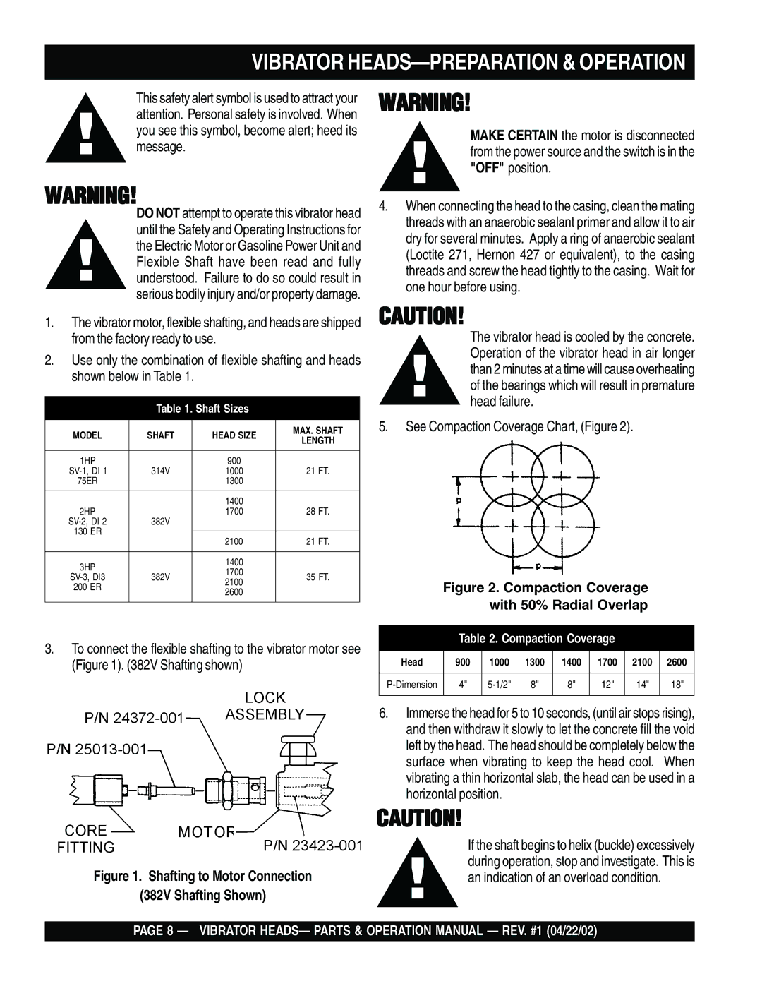
3.To connect the flexible shafting to the vibrator motor see (Figure 1). (382V Shafting shown)
Figure 1. Shafting to Motor Connection
(382V Shafting Shown)
CAUTION!
The vibrator head is cooled by the concrete. Operation of the vibrator head in air longer than 2 minutes at a time will cause overheating of the bearings which will result in premature head failure.
5.See Compaction Coverage Chart, (Figure 2).
| Figure 2. Compaction Coverage |
| |||||
|
| with 50% Radial Overlap |
| ||||
|
|
|
|
|
|
|
|
| Table 2. Compaction Coverage |
|
| ||||
|
|
|
|
|
|
|
|
Head | 900 | 1000 | 1300 | 1400 | 1700 | 2100 | 2600 |
|
|
|
|
|
|
|
|
4" | 8" | 8" | 12" | 14" | 18" | ||
|
|
|
|
|
|
|
|
6.Immerse the head for 5 to 10 seconds, (until air stops rising), and then withdraw it slowly to let the concrete fill the void left by the head. The head should be completely below the surface when vibrating to keep the head cool. When vibrating a thin horizontal slab, the head can be used in a horizontal position.
CAUTION!
If the shaft begins to helix (buckle) excessively during operation, stop and investigate. This is an indication of an overload condition.
PAGE 8 — VIBRATOR HEADS— PARTS & OPERATION MANUAL — REV. #1 (04/22/02)