MS-40H HYDRAULIC MIXER — CONTROLS
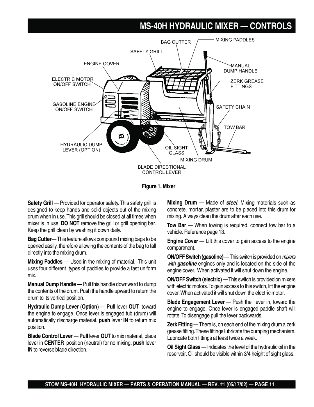
Figure 1. Mixer
Safety Grill — Provided for operator safety. This safety grill is designed to keep hands and solid objects out of the mixing drum when in use. This grill should be closed at all times when mixer is in use. DO NOT remove the grill or grill opening bar. Keep the grill clean by washing it down daily.
Bag Cutter— This feature allows compound mixing bags to be opened easily, therefore allowing the contents of the bag to fall directly into the mixing drum.
Mixing Paddles — Used in the mixing of material. This unit uses four different types of paddles to provide a fast uniform mix.
Manual Dump Handle — Pull this handle downward to dump the contents of the drum. Push the handle upward to return the drum to its vertical position.
Hydraulic Dump Lever (Option) — Pull lever OUT toward the engine to engage. Once lever is engaged tub (drum) will automatically discharge material. push lever IN to return mix position.
Blade Control Lever — Pull lever OUT to mix material, place lever in CENTER position (neutral) for no mixing, push lever IN to reverse blade direction.
Mixing Drum — Made of steel. Mixing materials such as concrete, mortar, plaster are to be placed into this drum for mixing. Always clean the drum after each use.
Tow Bar — When towing is required, connect tow bar to a vehicle. Reference page 13.
Engine Cover — Lift this cover to gain access to the engine compartment.
ON/OFF Switch (gasoline)
ON/OFF Switch (electric) — This switch is provided on mixers with electric motors.To gain access to this switch, lift the engine cover. When activated it will shut down the electric motor.
Blade Engagement Lever — Push the lever in, toward the engine to engage. Once lever is engaged paddle shaft will rotate. To disengage pull the lever backwards.
Zerk Fitting — There is, on each end of the mixing drum a zerk grease fitting.These fittings lubricate the dumping mechanism. Lubricate both fittings at least twice a week.
Oil Sight Glass — Indicates the level of the hydraulic oil in the reservoir. Oil should be visible within 3/4 height of sight glass.
STOW