7.Slide the Output Endbell (item 7) down onto the Armature/ Bearing Assembly (item 5) so the bearing engages the bearing pocket of the endbell and insulators seat properly on the Field.
8.Install the lockwashers and long screws through both endbells as shown and torque to
9.Place the motor assembly into the plastic housing half that has the threaded inserts. (item 1 Figure 11)
Field Orientation (Figure 9) (when viewed from the rear of the motor)
2
1
3
4
1.Lead to Switch
2.Lead to Brush Holder (Right Housing)
3.Lead to Brush Holder (Left Housing)
4.Lead to Switch
Figure 9. Field Orientation
SVA-SERIES — MAINTENANCE
Figure 10. Brush Leads
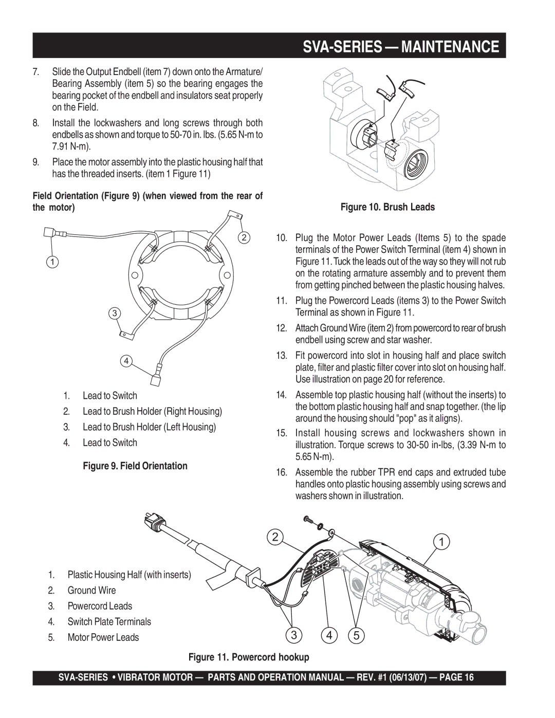
10.Plug the Motor Power Leads (Items 5) to the spade terminals of the Power Switch Terminal (item 4) shown in Figure 11.Tuck the leads out of the way so they will not rub on the rotating armature assembly and to prevent them from getting pinched between the plastic housing halves.
11.Plug the Powercord Leads (items 3) to the Power Switch Terminal as shown in Figure 11.
12.Attach Ground Wire (item 2) from powercord to rear of brush endbell using screw and star washer.
13.Fit powercord into slot in housing half and place switch plate, filter and plastic filter cover into slot on housing half. Use illustration on page 20 for reference.
14.Assemble top plastic housing half (without the inserts) to the bottom plastic housing half and snap together. (the lip around the housing should "pop" as it aligns).
15.Install housing screws and lockwashers shown in illustration. Torque screws to
16.Assemble the rubber TPR end caps and extruded tube handles onto plastic housing assembly using screws and washers shown in illustration.
1.Plastic Housing Half (with inserts)
2.Ground Wire
3.Powercord Leads
4.Switch Plate Terminals
5.Motor Power Leads
2 | 1 |
|
3 4 5