Once the desired one or two Model 45 units have been installed in a
a standard
4-Wire Audio Inputs and Outputs
Two audio line input and two audio line output signals are associated with the
4-Wire Line Inputs
As previously mentioned, the Model 45’s
and has an impedance of 13 k ohms. The line inputs are optimized for signals that have a nominal level of +4 dBu.
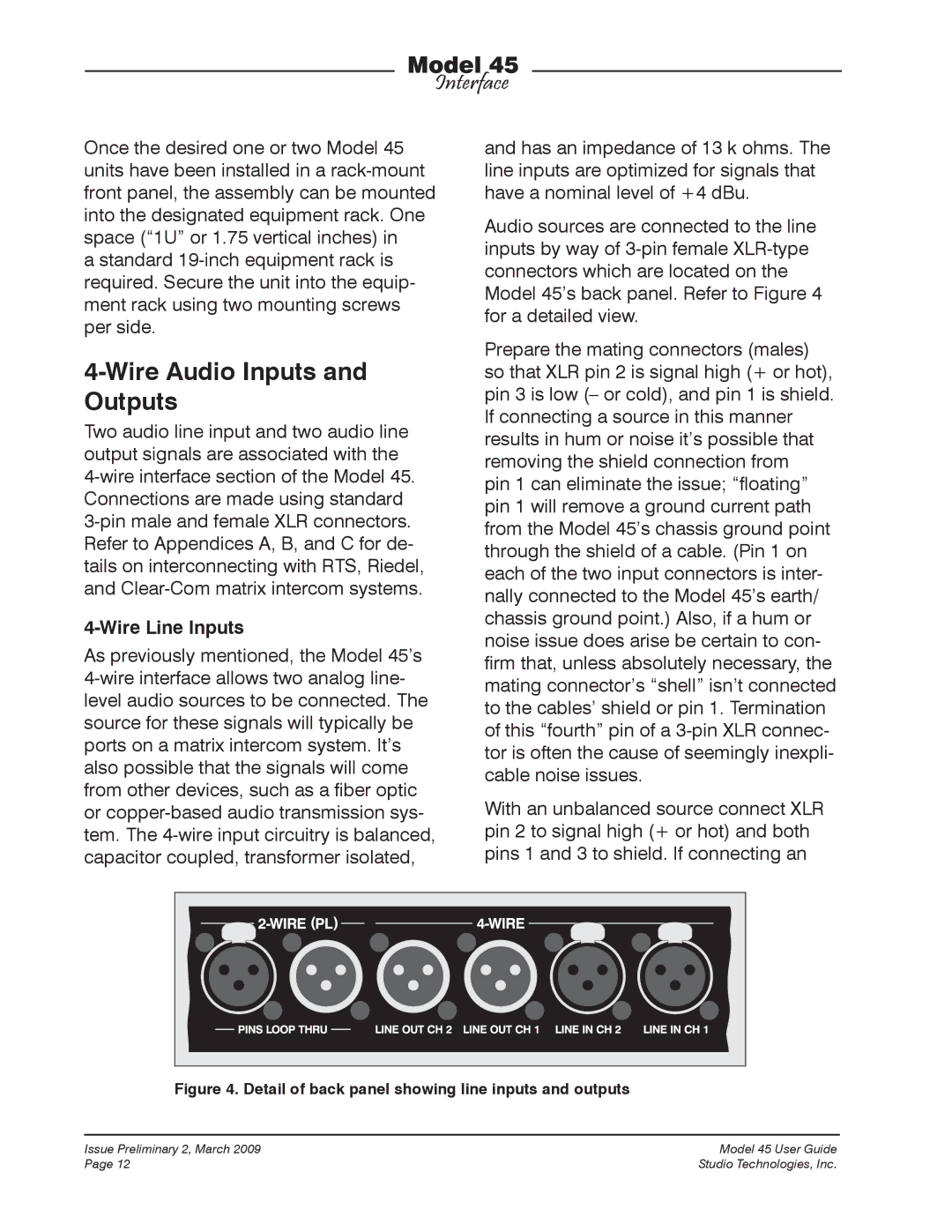
Audio sources are connected to the line inputs by way of
Prepare the mating connectors (males) so that XLR pin 2 is signal high (+ or hot), pin 3 is low (– or cold), and pin 1 is shield. If connecting a source in this manner results in hum or noise it’s possible that removing the shield connection from
pin 1 can eliminate the issue; “floating” pin 1 will remove a ground current path from the Model 45’s chassis ground point through the shield of a cable. (Pin 1 on each of the two input connectors is inter- nally connected to the Model 45’s earth/ chassis ground point.) Also, if a hum or noise issue does arise be certain to con- firm that, unless absolutely necessary, the mating connector’s “shell” isn’t connected to the cables’ shield or pin 1. Termination of this “fourth” pin of a
With an unbalanced source connect XLR pin 2 to signal high (+ or hot) and both pins 1 and 3 to shield. If connecting an
Figure 4. Detail of back panel showing line inputs and outputs
Issue Preliminary 2, March 2009 | Model 45 User Guide |
Page 12 | Studio Technologies, Inc. |