pin 3 of the Model 45’s 2-wire party-line intercom interface, will be utilized. Pin 2, the Model 45’s audio channel 1, will only be used for connecting DC power to the connected devices. While the audio resourc- es provided by channel 1 will not be used, the Model 45 can still be used to supply DC power on pin 2. As previously mentioned, the maximum current draw on the 30 volt DC output is 300 milliamperes. Alternatively, an external intercom power supply can support the connected devices.
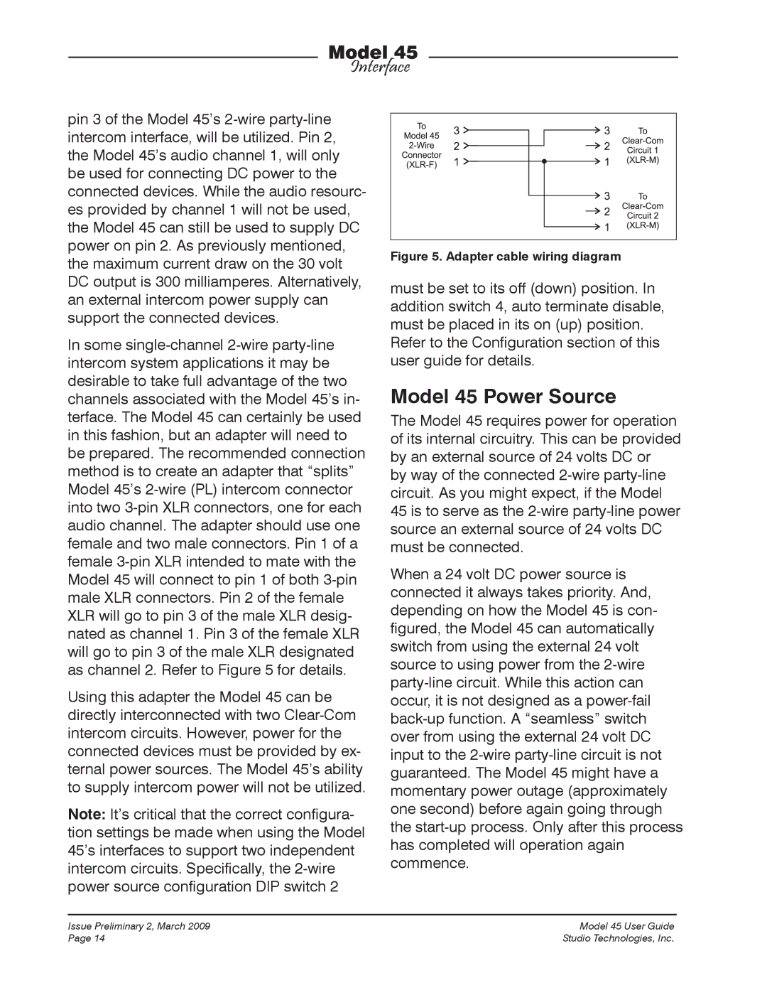
In some single-channel 2-wire party-line intercom system applications it may be desirable to take full advantage of the two channels associated with the Model 45’s in- terface. The Model 45 can certainly be used in this fashion, but an adapter will need to be prepared. The recommended connection method is to create an adapter that “splits” Model 45’s 2-wire (PL) intercom connector into two 3-pin XLR connectors, one for each audio channel. The adapter should use one female and two male connectors. Pin 1 of a female 3-pin XLR intended to mate with the Model 45 will connect to pin 1 of both 3-pin male XLR connectors. Pin 2 of the female XLR will go to pin 3 of the male XLR desig- nated as channel 1. Pin 3 of the female XLR will go to pin 3 of the male XLR designated as channel 2. Refer to Figure 5 for details.
Using this adapter the Model 45 can be directly interconnected with two Clear-Com intercom circuits. However, power for the connected devices must be provided by ex- ternal power sources. The Model 45’s ability to supply intercom power will not be utilized.
Note: It’s critical that the correct configura- tion settings be made when using the Model 45’s interfaces to support two independent intercom circuits. Specifically, the 2-wire power source configuration DIP switch 2
Figure 5. Adapter cable wiring diagram
must be set to its off (down) position. In addition switch 4, auto terminate disable, must be placed in its on (up) position. Refer to the Configuration section of this user guide for details.
Model 45 Power Source
The Model 45 requires power for operation of its internal circuitry. This can be provided by an external source of 24 volts DC or by way of the connected 2-wire party-line circuit. As you might expect, if the Model 45 is to serve as the 2-wire party-line power source an external source of 24 volts DC must be connected.
When a 24 volt DC power source is connected it always takes priority. And, depending on how the Model 45 is con- figured, the Model 45 can automatically switch from using the external 24 volt source to using power from the 2-wire party-line circuit. While this action can occur, it is not designed as a power-fail back-up function. A “seamless” switch over from using the external 24 volt DC input to the 2-wire party-line circuit is not guaranteed. The Model 45 might have a momentary power outage (approximately one second) before again going through the start-up process. Only after this process has completed will operation again commence.

