GAS INSTRUCTIONS | 5 |
|
|
BUILT-IN GAS LINE LOCATIONS
GENERAL CONSTRUCTION DETAILS
•Summit®
•All dimensions have a tolerance of plus or minus +/- 1/4” inch (6.35 mm).
Provide access for a corrugated gas line depending on the location of the side burner in relation to your main gas supply and regulator position.
Area should be kept clear of sharp, jagged, or extremely abrasive surfaces to avoid possible damage to gas supply lines. Exercise caution when pulling gas lines through
A 3/8 inch (9.52 mm) stainless steel corrugated gas line should be used to connect the side burner to the regulator accessory coupling.
TEST CONNECTIONS
All connections and joints must be thoroughly tested for leaks in accordance with local codes and all listed procedures in the latest edition of ANSI Z223.1/NFPA 54.
DANGER
Do not use an open flame to check for gas leaks. Be sure there are no sparks or open flames in the area while you check for gas leaks. This will result in a fire or explosion which can cause serious bodily injury or death, and damage to property.
WARNING: Do not use a rubber gas hose.
Be sure to secure the side burner unit with non corrosive screws anchored into the finished surface of the “island structure”. Replace the plastic plug on the front mounting hole to conceal the screw once side burner is secure.
1
1
2
2
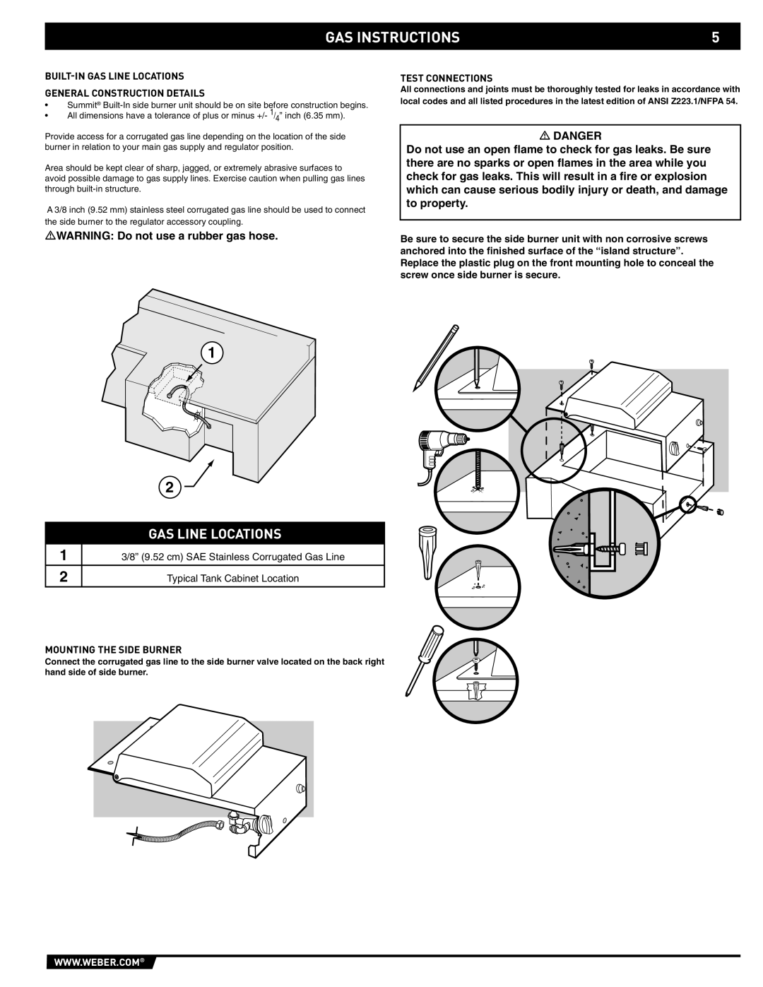
GAS LINE LOCATIONS
3/8” (9.52 cm) SAE Stainless Corrugated Gas Line
Typical Tank Cabinet Location
MOUNTING THE SIDE BURNER
Connect the corrugated gas line to the side burner valve located on the back right hand side of side burner.
WWW.WEBER.COM®