819-1207-11 specifications
Sun Microsystems 819-1207-11 is a prominent model that showcases the company's legacy in server and workstation innovation. As part of Sun Microsystems’ commitment to providing powerful computing solutions, this model highlights key features and technologies designed for demanding enterprise environments.One of the primary characteristics of the 819-1207-11 is its robust performance capabilities. Equipped with a high-speed processor architecture, this model supports multi-threading and multi-processing, allowing it to efficiently handle simultaneous tasks. This is particularly essential for businesses that rely on running numerous applications at once, ensuring high availability and responsiveness.
The 819-1207-11 is designed with extensive memory support, featuring scalability that can accommodate increased workloads as businesses grow. The architecture allows for ample RAM, which enhances the performance of memory-intensive applications, such as databases and enterprise resource planning (ERP) systems. This characteristic makes the system an appealing choice for organizations with evolving computing needs.
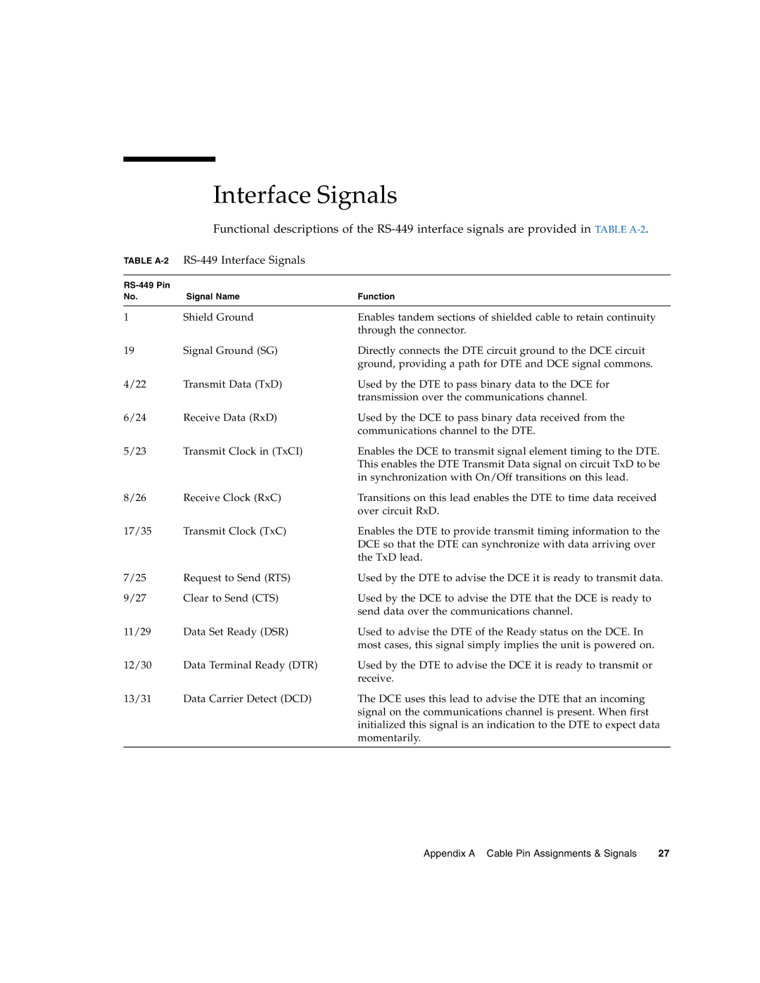
In terms of connectivity, the model is equipped with a variety of ports and interfaces that facilitate seamless integration into existing infrastructure. The incorporation of high-speed Ethernet support ensures fast data transfers and efficient network communication, which is vital for large data centers and cloud environments.
The storage capabilities of the 819-1207-11 also stand out. With support for advanced storage technologies such as RAID configurations, the system enhances data redundancy and performance. This is crucial for enterprise users who prioritize data integrity and availability.
Security features are also a hallmark of the 819-1207-11, with built-in mechanisms to safeguard sensitive information. Encryption technologies ensure that data at rest and during transmission is protected against unauthorized access, aligning with compliance requirements that many organizations must adhere to.
Furthermore, the system is designed with a focus on manageability. Integrated systems management tools allow IT departments to monitor performance, troubleshoot issues, and optimize resource allocation with ease. This simplifies operations, ultimately enhancing uptime and productivity.
Overall, the Sun Microsystems 819-1207-11 represents a blend of performance, scalability, and security, making it a compelling choice for businesses that require reliable computing solutions to drive their operations forward. Its technological advancements underscore the company's pivotal role in the evolution of enterprise computing.

