5017C-MTRF, 5017C-MTF specifications
Supermicro Computer has established itself as a leader in high-performance server solutions, and the Supermicro 5017C-MTF and 5017C-MTRF models exemplify the company's commitment to quality and innovation. These compact systems are designed for diverse applications, catering to both small and medium-sized enterprises as well as larger organizational needs.The Supermicro 5017C-MTF and 5017C-MTRF come equipped with a powerful Intel Xeon E3-1200 v6 processor, offering remarkable processing capabilities that enable users to run demanding applications with ease. These systems support up to 64GB of ECC DDR4 memory, ensuring data integrity and reliability crucial for mission-critical workloads. Moreover, the implementations of Intel's turbo boost technology allow for dynamic performance enhancements, enabling processors to scale up in speed as workload demands increase.
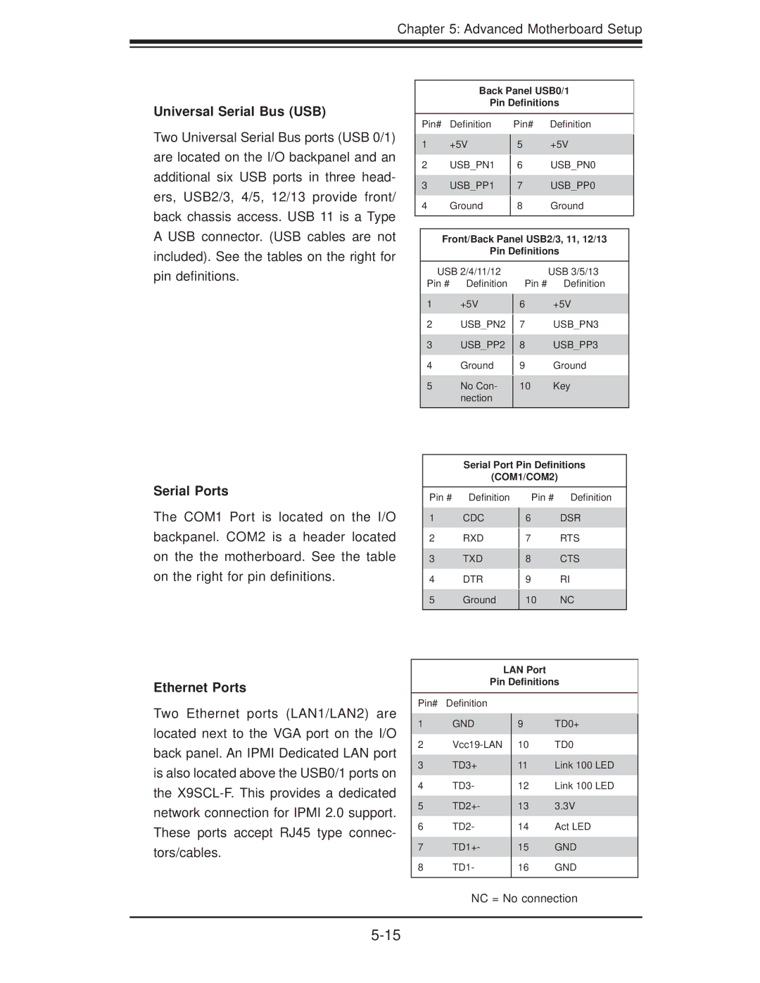
These models highlight Supermicro's commitment to flexibility and expandability. Both the 5017C-MTF and 5017C-MTRF include multiple PCIe slots so users can integrate various expansion cards according to their requirements. Additionally, the dual Gigabit Ethernet ports enhance networking capabilities, supporting multiple connectivity options to meet organizational demands.
Storage is an important aspect of any server solution, and these models do not disappoint. They offer support for multiple SATA drives and come with options for SSD integration for high-speed data access. This makes the 5017C-MTF and 5017C-MTRF well-suited for virtualization, cloud storage solutions, or even as a database server.
The systems also boast a compact and energy-efficient design, making them ideal for space-constrained environments. The 1U rackmount form factor allows for easy deployment in data center settings, while also promoting efficient airflow and cooling design. Furthermore, both models meet stringent energy efficiency standards, which can lead to significant power savings over time.
Security and remote management features are also key highlights of the 5017C-MTF and 5017C-MTRF. Supermicro’s Intelligent Management Technology (IMT) software allows administrators to monitor system health remotely and perform management tasks effectively.
In summary, the Supermicro 5017C-MTF and 5017C-MTRF present robust server solutions packed with cutting-edge technology, flexible expansion options, and a focus on efficiency and security, catering to the evolving needs of modern businesses.

