X7DVL-3 specifications
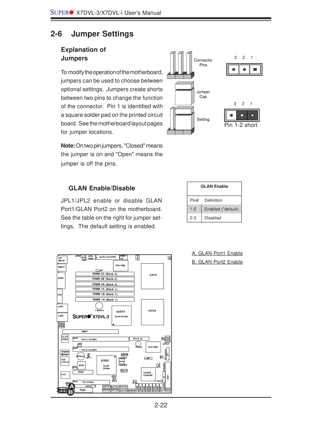
Super Micro Computer, Inc. is a well-respected name in the realm of high-performance computing, offering diverse solutions tailored for various applications. One of the notable offerings from the brand is the Supermicro X7DVL-3 motherboard, designed to provide exceptional performance and reliability for both workstations and servers.At its core, the X7DVL-3 is built on the Intel 5000X chipset, making it a robust choice for enterprise-level tasks. It supports Intel's dual-core and quad-core Xeon processors, specifically the LGA 771 socket. This design enables users to leverage enhanced processing power, facilitating intensive computational tasks such as virtualization, data analysis, or complex simulations.
One standout feature of the X7DVL-3 is its support for up to 32GB of DDR2 ECC (Error-Correcting Code) memory across four DIMM slots. This memory technology ensures higher reliability and stability, reducing the risk of data corruption—a critical factor for enterprises that require consistent performance and uptime.
In terms of connectivity, the motherboard comes equipped with 6 SATA ports, offering flexible storage options for RAID configurations, enhancing both speed and redundancy. Additionally, the X7DVL-3 features dual Gigabit Ethernet LAN ports, which facilitate high-speed network connectivity and allow for dual network path setups, ensuring seamless communication in network-intensive applications.
The X7DVL-3 is also designed with a high degree of scalability in mind. It includes multiple PCI-E slots, thereby supporting a range of expansion cards, including graphics cards for visualization tasks or additional networking options. This adaptability is crucial for organizations that need to upgrade or modify their systems as their operational demands evolve.
Another notable aspect of the Supermicro X7DVL-3 is its emphasis on efficiency and management. The motherboard is equipped with Supermicro’s IPMI (Intelligent Platform Management Interface) technology, allowing for remote management and monitoring of system health. This feature is particularly valuable in data center environments where managing multiple servers efficiently can lead to significant operational cost reductions.
In summary, the Supermicro X7DVL-3 motherboard stands out with its robust architecture, support for powerful Intel Xeon processors, extensive memory capacity, and advanced connectivity features. Coupled with its emphasis on reliability and manageability, this motherboard represents a solid choice for businesses seeking a dependable solution for their computing needs. Whether in a server configuration or a high-performance workstation, the X7DVL-3 delivers the performance and scalability critical for modern enterprises.

