TABLE OF CONTENTS |
|
|
General Information | page | 2 |
Inventory | page | 2 |
Tools Required | page | 2 |
Important Safety Information | page | 2 |
Codes | page | 3 |
Combustion and Ventilation Air | page | 3 |
Preinstallation | page | 4 |
Clearances | page | 4 |
Installation | page | 6 |
Gas Pressure Check | page | 6 |
Assembling the Logs | page | 7 |
Flame Appearance | page | 7 |
Cleaning and Servicing | page | 8 |
Replacement Parts | page | 8 |
Troubleshooting Guide | page | 9 |
Operating Instructions | page 10 | |
Replacement Parts List | page 12 | |
GENERAL INFORMATION
These
These log heaters are either thermostatic
A spark ignition system (piezo) allows the gas pilot to be lit without the use of matches or batteries and permits operation of the heater during a power outage.
These heaters are fitted with a specially de- signed pilot utilizing an oxygen depletion sen- sor (ODS) which responds to the amount of oxygen available in the room and shuts the heater off before the oxygen level drops below 18%.
The pilot can be relit only when fresh air is available. Refer to the Combustion and Ventila- tion Air section.
WARNING: THIS APPLIANCE IS FOR IN- STALLATION IN A SOLID FUEL BURN- ING FIREPLACE WITH A WORKING FLUE OR AN APPROVED VENTLESS FIREBOX ENCLOSURE ONLY.
Minimum Fireplace (Firebox) Size
Height | Depth | Width |
|
|
|
16" | 18" | 28" Front |
|
|
|
Table 1
Do not install these
Check the inventory list to be sure that you have all the necessary parts in usable condition. Also check for concealed damage.
WARNING: FAILURE TO INSTALL THESE LOGS EXACTLY AS DETAILED IN THIS INSTRUCTION MANUAL MAY RESULT IN SOOTING AND MAY RESULT IN VOIDING PRODUCT WARRANTIES.
Inventory
Unvented gas log room heater Bag of decorative volcanic rock Ceramic fiber logs
Installation and Operating Instructions
Tools and Supplies Normally Required
External regulator (Propane models only) Manual
Sediment trap
Piping complying with local codes Pipe compound
Pipe wrench Tee joint Screwdriver
IMPORTANT SAFETY INFORMATION
INSTALLER: PLEASE LEAVE THESE INSTRUC- TIONS WITH THE OWNER.
OWNER: PLEASE RETAIN THESE INSTRUC- TION FOR FUTURE REFERENCE.
WARNING: ANY CHANGE TO THIS ROOM HEATER OR ITS CONTROLS CAN BE DAN- GEROUS. IMPROPER INSTALLATION OR USE OF THIS HEATER CAN CAUSE SERI- OUS INJURY OR DEATH FROM FIRE, BURNS, EXPLOSION OR CARBON MON- OXIDE POISONING.
Carbon Monoxide Poisoning: Early signs of carbon monoxide poisoning are similar to the flu with headaches, dizziness and/or nausea. If you have these signs, obtain fresh air im- mediately. Have the Unvented Gas Heater serviced as it may not be operating correctly.
•Due to high temperatures, the heater should be located out of traffic and away from furniture and draperies.
•Children and adults should be alerted to the hazard of high surface temperature and should stay away to avoid burns or clothing ignition.
•Young children should be carefully super- vised when they are in the same room with the heater.
•Do not place clothing or other flammable material on or near the heater.
•Any safety screen or guard removed for servicing the heater must be replaced prior to operating the heater.
•Installation and repair should be done by a qualified service person. The heater should be inspected before use and at least annually by a professionalserviceperson. More frequentclean- ing may be required due to excessive lint from carpeting, bedding material, etc. It is important that control compartments, burners and circulat- ing air passageways of the heater be kept clean.
2
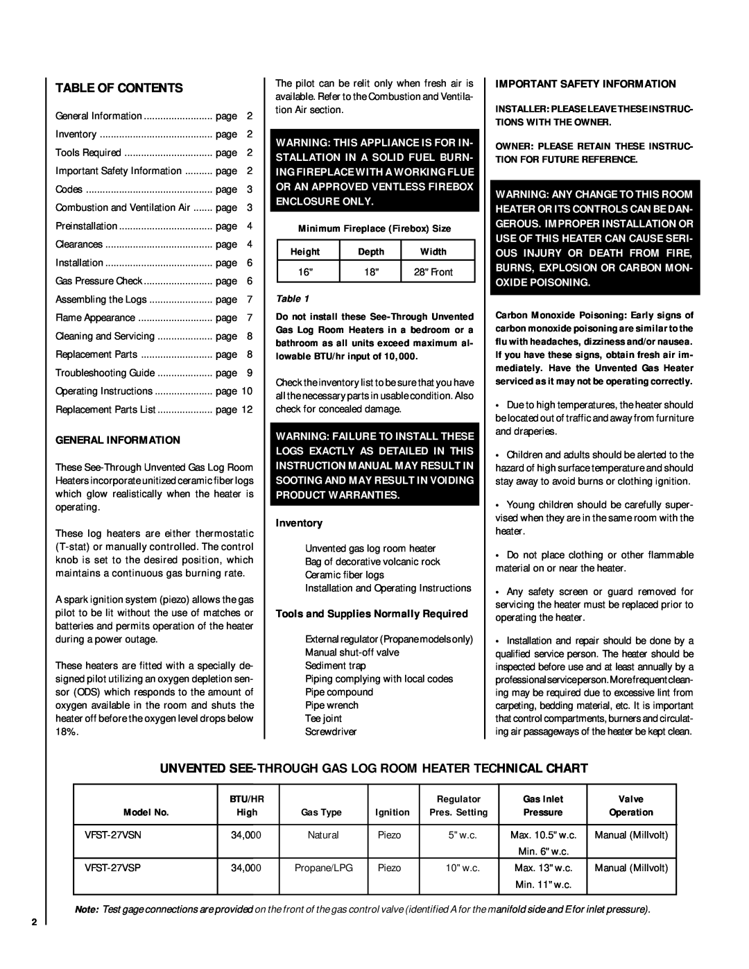
UNVENTED
| BTU/HR |
|
| Regulator | Gas Inlet | Valve |
Model No. | High | Gas Type | Ignition | Pres. Setting | Pressure | Operation |
|
|
|
|
|
|
|
34,000 | Natural | Piezo | 5" w.c. | Max. 10.5" w.c. | Manual (Millvolt) | |
|
|
|
|
| Min. 6" w.c. |
|
34,000 | Propane/LPG | Piezo | 10" w.c. | Max. 13" w.c. | Manual (Millvolt) | |
|
|
|
|
| Min. 11" w.c. |
|
|
|
|
|
|
|
|
Note: Test gage connections are provided on the front of the gas control valve (identified A for the manifold side and E for inlet pressure).