ADJUSTING THE DRIVE CONTROLS
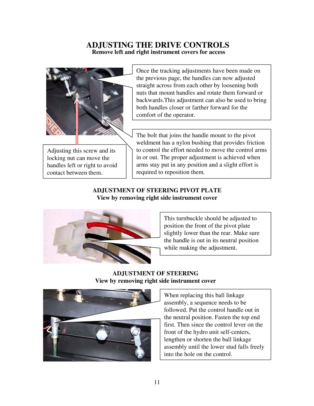
Remove left and right instrument covers for access
Adjusting this screw and its locking nut can move the handles left or right to avoid contact between them.
Once the tracking adjustments have been made on the previous page, the handles can now adjusted straight across from each other by loosening both nuts that mount handles and rotate them forward or backwards.This adjustment can also be used to bring both handles closer or farther forward for the comfort of the operator.
The bolt that joins the handle mount to the pivot weldment has a nylon bushing that provides friction to control the effort needed to move the control arms in or out. The proper adjustment is achieved when arms stay put in any position and a slight effort is required to reposition them.
ADJUSTMENT OF STEERING PIVOT PLATE View by removing right side instrument cover
This turnbuckle should be adjusted to position the front of the pivot plate slightly lower than the rear. Make sure the handle is out in its neutral position while making the adjustment.
ADJUSTMENT OF STEERING
View by removing right side instrument cover
When replacing this ball linkage assembly, a sequence needs to be followed. Put the control handle out in the neutral position. Fasten the top end first. Then since the control lever on the front of the hydro unit
11