California Blonde specifications
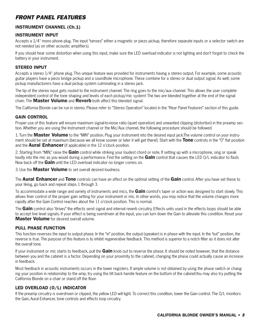
The SWR Sound California Blonde is a revered amplifier known for its rich tonal capabilities and reliable performance, especially favored by acoustic musicians and guitarists. This powerful amp is designed to cater to the unique needs of acoustic instruments, making it a popular choice for singer-songwriters, live performers, and studio musicians alike.At the heart of the California Blonde is its impressive 200-watt power rating, which ensures that players can achieve a robust sound that fills the room without sacrificing clarity. The amp comes equipped with two high-quality speakers that deliver a magnetic blend of warmth and articulation, allowing acoustic guitars and vocals to shine through with remarkable detail.
One of the standout features of the California Blonde is its advanced EQ section. The amp includes a 3-band EQ, which allows musicians to tweak the frequency response and tailor their sound to suit various performance environments. This level of control is essential for acoustic musicians looking to enhance the natural tone of their instruments. Additionally, the amp features a built-in chorus effect that can add depth and dimension to the sound, perfect for lush, layered performances.
The California Blonde also possesses dual channels, enabling users to connect multiple instruments or microphones simultaneously. Each channel features its own gain control and EQ, offering the flexibility to manage different sources effectively and deliver a balanced mix. This is particularly useful for duos or bands that wish to amplify their sound without the need for a complex setup.
Another notable characteristic is the amp's lightweight and portable design. Although it is robust enough for gigging, the California Blonde is easy to transport, making it ideal for musicians on the go. The durable cabinet construction ensures that the amp can withstand the rigors of frequent travel while maintaining its performance integrity.
Overall, the SWR Sound California Blonde is a quintessential amplifier that combines power, versatility, and sonic fidelity. Its thoughtful design and musician-centric features make it a sought-after choice for those looking to elevate their acoustic sound, whether on stage or in the studio. With its ability to produce rich, full tones that honor the acoustic instrument’s natural sound, the California Blonde continues to be a trusted tool for artists across various genres.
