PREPARATION FOR USE
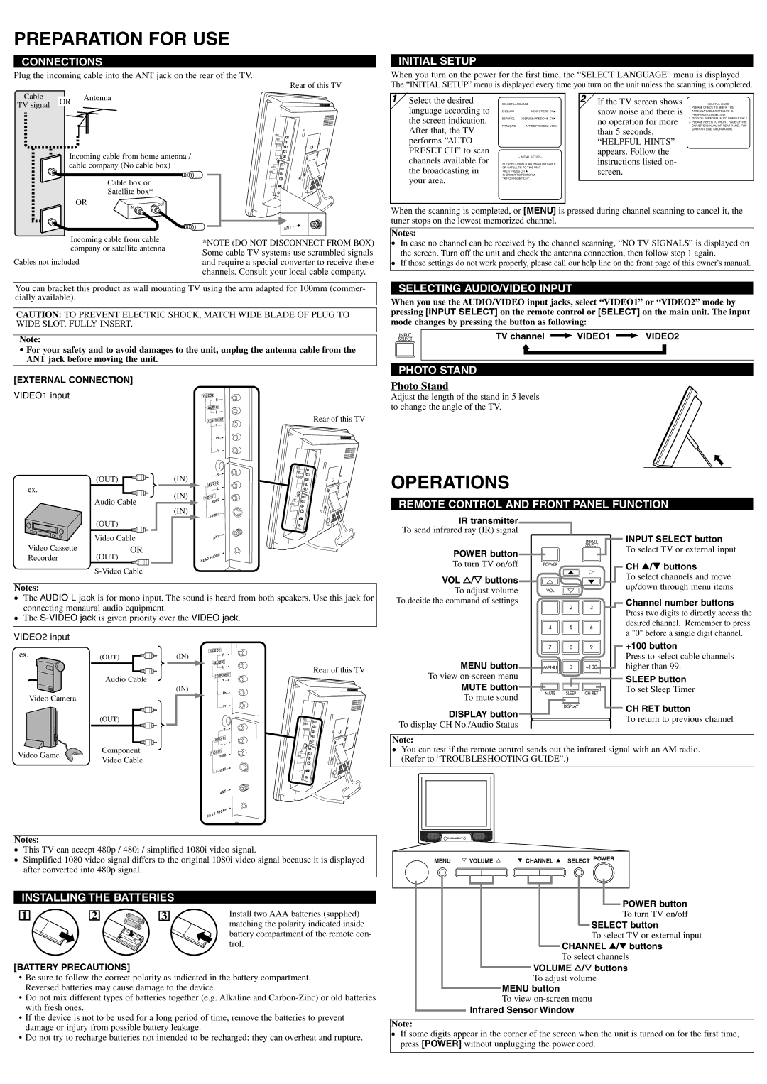
CONNECTIONS
Plug the incoming cable into the ANT jack on the rear of the TV.
Rear of this TV
Cable |
| Antenna | |
OR | |||
TV signal |
| ||
|
|
INITIAL SETUP
When you turn on the power for the first time, the “SELECT LANGUAGE” menu is displayed. The “INITIAL SETUP” menu is displayed every time you turn on the unit unless the scanning is completed.
1 Select the desired | SELECT LANGUAGE | 2 If the TV screen shows | - HELPFUL HINTS - | ||
language according to |
|
| snow noise and there is | 1. PLEASE CHECK TO SEE IF THE | |
ENGLISH | NEXT:PRESS CHK | ANTENNA/CABLE/SATELLITE IS | |||
|
| PROPERLY CONNECTED. | |||
the screen indication. | ESPAÑOL | DESPUÉS:PRESIONE CHL | no operation for more | 2. DID YOU PERFORM “AUTO PRESET CH” ? | |
|
| 3. PLEASE REFER TO FRONT PAGE OF THE | |||
FRANÇAIS | APRÈS:PRESSEZ VOLX | OWNER’S MANUAL OR REAR PANEL FOR | |||
After that, the TV | than 5 seconds, | ||||
|
| SUPPORT LINE INFORMATION. | |||
|
|
| |||
Incoming cable from home antenna / cable company (No cable box)
Cable box or
Satellite box*
OR | OUT |
| IN |
Incoming cable from cable company or satellite antenna
Cables not included
AUDIO
COMPONENT
ANT
ANT
*NOTE (DO NOT DISCONNECT FROM BOX) Some cable TV systems use scrambled signals and require a special converter to receive these channels. Consult your local cable company.
performs “AUTO |
| “HELPFUL HINTS” |
PRESET CH” to scan |
| appears. Follow the |
channels available for | – INITIAL SETUP – | instructions listed on- |
PLEASE CONNECT ANTENNA OR CABLE | ||
the broadcasting in | OR SATELLITE TO THIS UNIT. | screen. |
THEN PRESS CH K, | ||
IN ORDER TO PERFORM | ||
your area. | “AUTO PRESET CH ”. |
|
|
|
When the scanning is completed, or [MENU] is pressed during channel scanning to cancel it, the tuner stops on the lowest memorized channel.
Notes:
●In case no channel can be received by the channel scanning, “NO TV SIGNALS” is displayed on the screen. Turn off the unit and check the antenna connection, then follow step 1 again.
●If those settings do not work properly, please call our help line on the front page of this owner's manual.
You can bracket this product as wall mounting TV using the arm adapted for 100mm (commer- cially available).
CAUTION: TO PREVENT ELECTRIC SHOCK, MATCH WIDE BLADE OF PLUG TO WIDE SLOT, FULLY INSERT.
Note:
•For your safety and to avoid damages to the unit, unplug the antenna cable from the ANT jack before moving the unit.
SELECTING AUDIO/VIDEO INPUT
When you use the AUDIO/VIDEO input jacks, select “VIDEO1” or “VIDEO2” mode by pressing [INPUT SELECT] on the remote control or [SELECT] on the main unit. The input mode changes by pressing the button as following:
INPUT | TV channel | VIDEO1 | VIDEO2 |
SELECT |
PHOTO STAND
[EXTERNAL CONNECTION]
VIDEO1 input
(OUT) |
ex. |
Audio Cable |
(OUT) |
(IN)
(IN)
(IN)
VIDEO2 |
| R | |
|
| ||
AUDIO | |||
|
| L | |
COMPONENT | |||
|
| Y | |
|
| Pb | |
|
| Pr | |
|
| R | |
AUDIO | |||
|
| L | |
VIDEO1 | EO | ||
VID | |||
| |||
IDEO | |||
|
| ||
Rear of this TV
AUDIO
COMPONENT
ANT
Photo Stand
Adjust the length of the stand in 5 levels to change the angle of the TV.
OPERATIONS
REMOTE CONTROL AND FRONT PANEL FUNCTION
IR transmitter
| Video Cable |
Video Cassette | OR |
Recorder | (OUT) |
|
AN | T |
PHONE | |
HEAD |
|
To send infrared ray (IR) signal
|
| INPUT |
|
| SELECT |
POWER button |
|
|
To turn TV on/off | POWER |
|
VOL X/Y buttons | o | CH |
m | p |
INPUT SELECT button
To select TV or external input
CH K/L buttons
To select channels and move
Notes:
●The AUDIO L jack is for mono input. The sound is heard from both speakers. Use this jack for connecting monaural audio equipment.
●The
VIDEO2 input
To adjust volume | VOL | n |
|
To decide the command of settings | 1 | 2 | 3 |
| |||
| 4 | 5 | 6 |
| 7 | 8 | 9 |
up/down through menu items
Channel number buttons
Press two digits to directly access the desired channel. Remember to press a "0" before a single digit channel.
+100 button
ex.(OUT)
Audio Cable
Video Camera
(IN)
(IN)
VIDEO2 |
R |
AUDIO |
L |
COMPONENT |
Y |
Pb |
Rear of this TV
MENU button | MENU | 0 | +100 | |
To view |
|
|
| |
MUTE button | MUTE | SLEEP | CH RET | |
To mute sound | ||||
|
|
|
Press to select cable channels higher than 99.
SLEEP button
To set Sleep Timer
(OUT)
Pr |
R |
AUDIO |
L |
AUDIO
COMPONENT
| DISPLAY | CH RET button |
DISPLAY button |
| |
| To return to previous channel | |
To display CH No./Audio Status |
| |
|
| |
|
|
|
Note:
Video Game
Component Video Cable
VIDEO1 | EO | ||
VID | |||
| |||
IDEO | |||
ANT
●You can test if the remote control sends out the infrared signal with an AM radio. (Refer to “TROUBLESHOOTING GUIDE”.)
ANT
PHONE
HEAD
Notes:
●This TV can accept 480p / 480i / simplified 1080i video signal.
●Simplified 1080 video signal differs to the original 1080i video signal because it is displayed after converted into 480p signal.
INSTALLING THE BATTERIES |
| ||
1 | 2 | 3 | Install two AAA batteries (supplied) |
|
|
| matching the polarity indicated inside |
|
|
| battery compartment of the remote con- |
|
|
| trol. |
[BATTERY PRECAUTIONS]
•Be sure to follow the correct polarity as indicated in the battery compartment. Reversed batteries may cause damage to the device.
•Do not mix different types of batteries together (e.g. Alkaline and
•If the device is not to be used for a long period of time, remove the batteries to prevent damage or injury from possible battery leakage.
•Do not try to recharge batteries not intended to be recharged; they can overheat and rupture.
MENU Y VOLUME X | L CHANNEL K SELECT POWER |
POWER button
To turn TV on/off
SELECT button
To select TV or external input
CHANNEL K/L buttons
To select channels
VOLUME X/Y buttons
To adjust volume
MENU button
To view
Infrared Sensor Window
Note:
●If some digits appear in the corner of the screen when the unit is turned on for the first time, press [POWER] without unplugging the power cord.