PRECAUTIONS
Install Location
For safety and optimum performance of your VCR:
•Install the VCR in a horizontal and stable position. Do not place anything directly on top of the VCR. Do not place the VCR directly on top of the TV.
•Shield it from direct sunlight and keep it away from sources of intense heat. Avoid dusty or humid places. Avoid places with insuffi- cient ventilation for proper heat dissipation. Do not block the ventila- tion holes on the sides of the VCR. Avoid locations subject to strong vibration or strong magnetic fields.
Avoid the Hazards of Electrical Shock and Fire
•Do not handle the power cord with wet hands.
•Do not pull on the power cord when disconnecting it from AC wall outlet. Grasp it by the plug.
Moisture Condensation Warning
Moisture condensation may occur inside the unit when it is moved from a cold place to a warm place, or after heating a cold room or under conditions of high humidity. Do not use the VCR at least for 2 hours until its inside is dry.
FCC Warning
This equipment may generate or use radio frequency energy. Changes or modifications to this equipment may cause harmful inter- ference unless the modifications are expressly approved in the instruction manual. The user could lose the authority to operate this equipment if an unauthorized change or modification is made.
Important Copyright Information
Unauthorized recording or use of broadcast television programming, video tape, film or other copyrighted material may violate applicable copyright laws. We assume no responsibility for the unauthorized duplication, use, or other acts which infringe upon the rights of copy- right owners.
A Note about Recycling
This product's packaging materials are recyclable and can be reused. Please dispose of any materials in accordance with your local recy- cling regulations. Batteries should never be thrown away or incinerat- ed but disposed of in accordance with your local regulations concern- ing chemical wastes.
Note to the Cable TV System Installer
This reminder is provided to call the Cable TV system installer’s attention to Article
CAUTION:
TO PREVENT ELECTRIC SHOCK, MATCH WIDE BLADE OF PLUG TO WIDE SLOT, FULLY INSERT.
ATTENTION:
POUR ÉVITER LES CHOC ÉLECTRIQUES, INTRODUIRE LA LAME LA PLUS LARGE DE LA FICHE DANS LA BORNE COR- RESPONDANTE DE LA PRISE ET POUSSER JUSQU’AU FOND.
DESCRIPTION OF CONTROLS
Front Panel |
|
| 1 |
|
|
|
| |
|
|
|
|
|
|
|
| |
| POWER |
|
|
| STOP/EJECT | PLAY | F.FWD | |
|
| CHANNEL |
|
| REC/OTR |
|
| |
|
|
|
|
|
| EW |
| |
|
|
|
|
| MENU |
| R |
|
VIDEO | AUDIO |
|
|
|
|
|
|
|
|
|
|
| POWER VCR/TV TAPE IN TIMER | REC |
|
|
|
1 3 | 1 2 | 1 1 1 0 | 9 | 8 | 7 6 | 5 | 4 3 2 | |
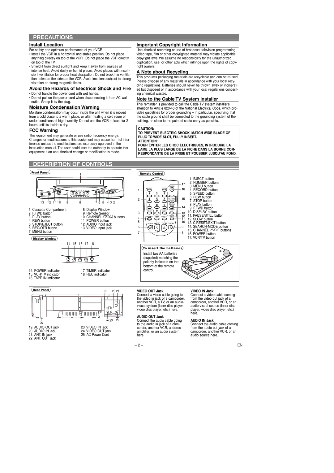
1. Cassette Compartment | 18. Display Window |
| ||||||
2. F.FWD button |
|
| 19. Remote Sensor | ) buttons | ||||
3. PLAY button |
|
| 10. CHANNEL ( |
| ||||
4. REW button |
|
| 11. POWER button |
| ||||
5. STOP/EJECT button |
| 12. AUDIO Input jack |
| |||||
6. REC/OTR button |
| 13. VIDEO Input jack |
| |||||
7. MENU button |
|
|
|
|
|
|
| |
Display Window
Remote Control
|
|
|
| POWER |
1 | EJECT |
| VCR / TV |
|
1 | 2 | 3 |
| |
|
| |||
2 | 4 | 5 | 6 | CHANNEL |
| 7 | 8 | 9 | SEARCH |
| ||||
| MENU | 0 | SLOW | C.RESET |
3 | EXIT | |||
|
|
| PAUSE | |
| RECORD | SPEED | DISPLAY | |
4 | /STILL | |||
|
|
|
| |
5 | REW | STOP | PLAY | F.FWD |
6
7
1. EJECT button
172. NUMBER buttons
3. MENU button
164. RECORD button
5. SPEED button
156. REW button
7.STOP button
8.PLAY button
149. F.FWD button
1310. DISPLAY button
1211. PAUSE/STILL button
1112. SLOW button
1013. C.RESET/EXIT button
914.
15.CHANNEL (![]() ) buttons
) buttons
816. POWER button
17. VCR/TV button
14 15 16 17 18
POWER | VCR/TV | TAPE IN | TIMER | REC |
14. POWER indicator | 17. TIMER indicator |
15. VCR/TV indicator | 18. REC indicator |
16. TAPE IN indicator |
|
To insert the batteries |
Install two AA batteries |
(supplied) matching the |
polarity indicated on the |
bottom of the remote |
control. |
Rear Panel
25
19.AUDIO OUT jack
20.AUDIO IN jack
21.ANT. IN jack
22.ANT. OUT jack
19 | 20 21 |
| ANT |
| IN |
AUDIO | |
OUT | IN |
| OUT |
VIDEO | |
24 23 22
23.VIDEO IN jack
24.VIDEO OUT jack
25.AC Power Cord
VIDEO OUT Jack
Connect a video cable going to the video in jack of a camcorder, another VCR, a TV, or an audio- visual system (laser disc player, video disc player, etc.) here.
AUDIO OUT Jack
Connect the audio cable going to the audio in jack of a cam- corder, another VCR, a stereo amplifier, or an audio system here.
VIDEO IN Jack
Connect a video cable coming from the video out jack of a camcorder, another VCR, or an
AUDIO IN Jack
Connect the audio cable coming from the audio out jack of a camcorder, another VCR, or an audio source here.
– 2 – | EN |