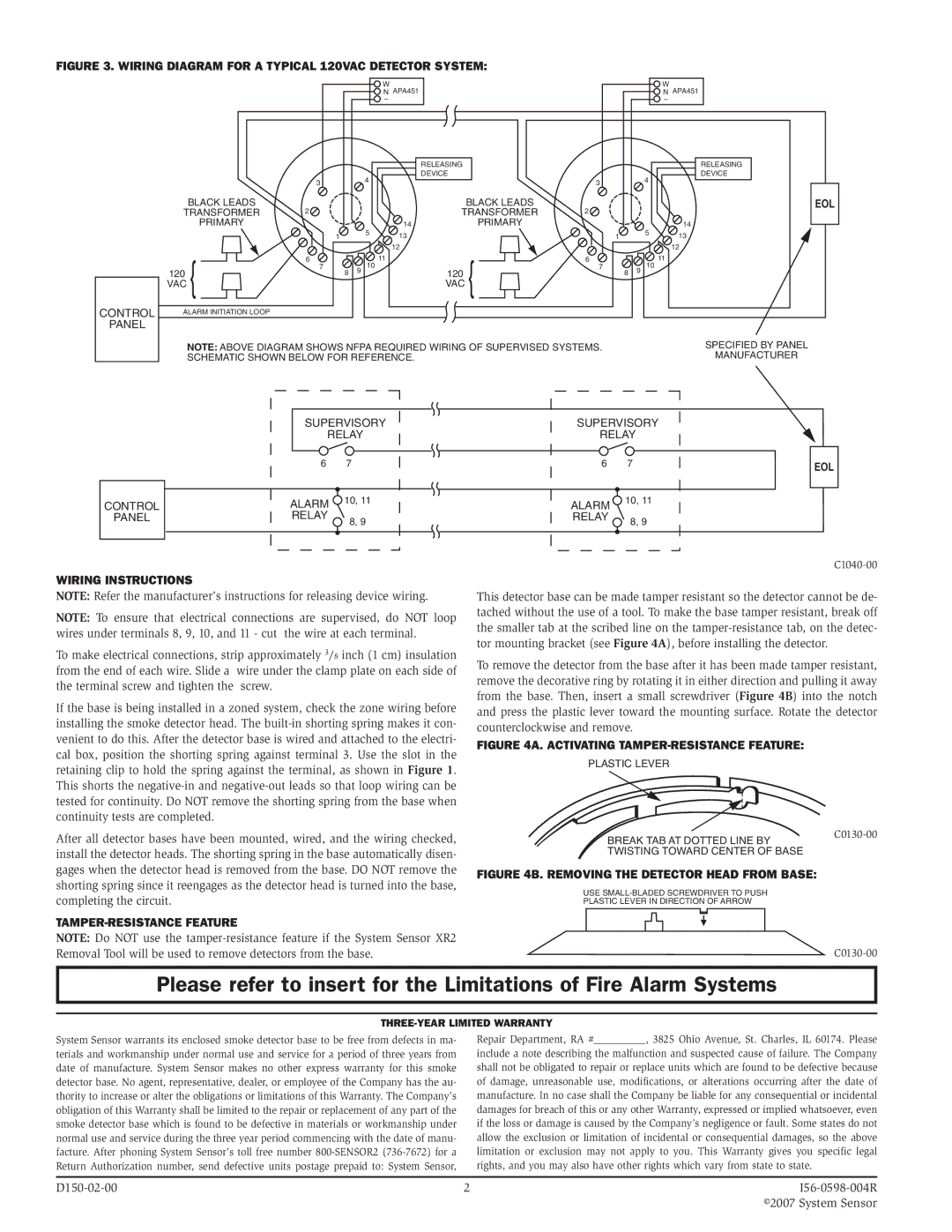
Figure 3. Wiring diagram for a typical 120VAC detector system:
W |
N APA451 |
– |
W
NAPA451
–
|
| RELEASING |
|
|
| DEVICE |
|
| 3 | 4 | 3 |
|
| ||
BLACK LEADS |
| BLACK LEADS |
|
TRANSFORMER | 2 | TRANSFORMER | 2 |
4
RELEASING
DEVICE
EOL
| PRIMARY |
|
|
|
| 14 |
| PRIMARY |
|
|
| 1 |
| 5 | 13 |
|
|
|
|
|
|
|
|
| ||
|
|
|
|
|
| 12 |
|
|
|
| 6 |
|
| 11 |
|
| 6 |
| 120 | 7 | 8 | 9 | 10 |
| 120 | 7 |
|
|
|
|
| ||||
| VAC |
|
|
|
|
| VAC |
|
CONTROL | ALARM INITIATION LOOP |
|
|
|
|
|
|
|
PANEL |
|
|
|
|
|
|
|
|
NOTE: ABOVE DIAGRAM SHOWS NFPA REQUIRED WIRING OF SUPERVISED SYSTEMS. SCHEMATIC SHOWN BELOW FOR REFERENCE.
14
1 5 13
12
11
8 9 10
SPECIFIED BY PANEL
MANUFACTURER
CONTROL
PANEL
SUPERVISORY
RELAY
6 7
ALARM ![]() 10, 11 RELAY
10, 11 RELAY ![]() 8, 9
8, 9
SUPERVISORY
RELAY
6 7
ALARM ![]() 10, 11 RELAY
10, 11 RELAY ![]() 8, 9
8, 9
EOL
Wiring Instructions
NOTE: Refer the manufacturer’s instructions for releasing device wiring.
NOTE: To ensure that electrical connections are supervised, do NOT loop wires under terminals 8, 9, 10, and 11 - cut the wire at each terminal.
To make electrical connections, strip approximately 3/8 inch (1 cm) insulation from the end of each wire. Slide a wire under the clamp plate on each side of the terminal screw and tighten the screw.
If the base is being installed in a zoned system, check the zone wiring before installing the smoke detector head. The
After all detector bases have been mounted, wired, and the wiring checked, install the detector heads. The shorting spring in the base automatically disen- gages when the detector head is removed from the base. DO NOT remove the shorting spring since it reengages as the detector head is turned into the base, completing the circuit.
Tamper-resistance Feature
NOTE: Do NOT use the
This detector base can be made tamper resistant so the detector cannot be de- tached without the use of a tool. To make the base tamper resistant, break off the smaller tab at the scribed line on the
To remove the detector from the base after it has been made tamper resistant, remove the decorative ring by rotating it in either direction and pulling it away from the base. Then, insert a small screwdriver (Figure 4B) into the notch and press the plastic lever toward the mounting surface. Rotate the detector counterclockwise and remove.
Figure 4A. Activating tamper-resistance feature:
PLASTIC LEVER
BREAK TAB AT DOTTED LINE BY | |
| |
TWISTING TOWARD CENTER OF BASE |
|
Figure 4B. Removing the detector head from base:
USE
PLASTIC LEVER IN DIRECTION OF ARROW
Please refer to insert for the Limitations of Fire Alarm Systems
Three-Year Limited Warranty
System Sensor warrants its enclosed smoke detector base to be free from defects in ma- terials and workmanship under normal use and service for a period of three years from date of manufacture. System Sensor makes no other express warranty for this smoke detector base. No agent, representative, dealer, or employee of the Company has the au- thority to increase or alter the obligations or limitations of this Warranty. The Company’s obligation of this Warranty shall be limited to the repair or replacement of any part of the smoke detector base which is found to be defective in materials or workmanship under normal use and service during the three year period commencing with the date of manu- facture. After phoning System Sensor’s toll free number
Repair Department, RA #__________, 3825 Ohio Avenue, St. Charles, IL 60174. Please
include a note describing the malfunction and suspected cause of failure. The Company shall not be obligated to repair or replace units which are found to be defective because of damage, unreasonable use, modifications, or alterations occurring after the date of manufacture. In no case shall the Company be liable for any consequential or incidental damages for breach of this or any other Warranty, expressed or implied whatsoever, even if the loss or damage is caused by the Company’s negligence or fault. Some states do not allow the exclusion or limitation of incidental or consequential damages, so the above limitation or exclusion may not apply to you. This Warranty gives you specific legal rights, and you may also have other rights which vary from state to state.
2 | ||
|
| ©2007 System Sensor |