INSTALLATION AND MAINTENANCE INSTRUCTIONS
B114LP Plug-in Detector Base
For use with the following smoke detectors: US - 1151, 2151, 2151T; CANADA - 1151A, 2151A, 2151TA; EUROPE - 1151E, 2151E
3825 Ohio Avenue, St. Charles, Illinois 60174
Specifications |
|
Base Diameter: | 6.2 in (157 mm) |
Base Height: | 0.95 in (24 mm) |
Weight: | 0.6 lb (274 g) |
Mounting: | 4˝ square box with or without plaster ring, minimum depth 1.5˝; 4˝ octagon box, minimum depth 1.5˝; |
| 31⁄2˝ octagon box, minimum depth 1.5˝; 31⁄2˝ octagon box, minimum depth 1.5˝ |
Operating Temperature Range: | 0°C to 49°C (32°F to 120°F) |
Operating Humidity Range: | 10% to 93% Relative Humidity |
Electrical Ratings (includes base and detector) | |
System Voltage: | 120 VAC, 60 Hz |
Relay Contact Ratings Resistive Load: | Form A — 2.0A @ 30VAC/DC; Form C — 2.0A @ 30VAC/DC, 1.0A @ 125VAC |
| (If used, the RA400 Remote Annunciator and RTC operates within the specified detector system voltage) |
36.0 seconds maximum | |
Before Installing
Please thoroughly read the System Sensor manual
NOTICE: This manual should be left with the owner/user of this equipment.
IMPORTANT: The detector used with this base must be tested and maintained regularly following NFPA 72 requirements. The detector used with this base should be cleaned at least once a year.
General Description
The model B114LP detector base is designed for use with System Sensor model 2151 photoelectronic and 1151 ionization detector heads. This
Mounting
The detector base mounts directly to
nect smoke detectors to control panels and accessory devices should be color- coded to reduce the likelihood of wiring errors. Improper connections can prevent a system from responding properly in the event of a fire.
For signal wiring (the wiring between interconnected detectors), it is recom- mended that the wire be no smaller than AWG 18. However, the screws and clamping plate in the base can accommodate wire sizes up to AWG 12. The use of twisted pair wiring for the power (+ and
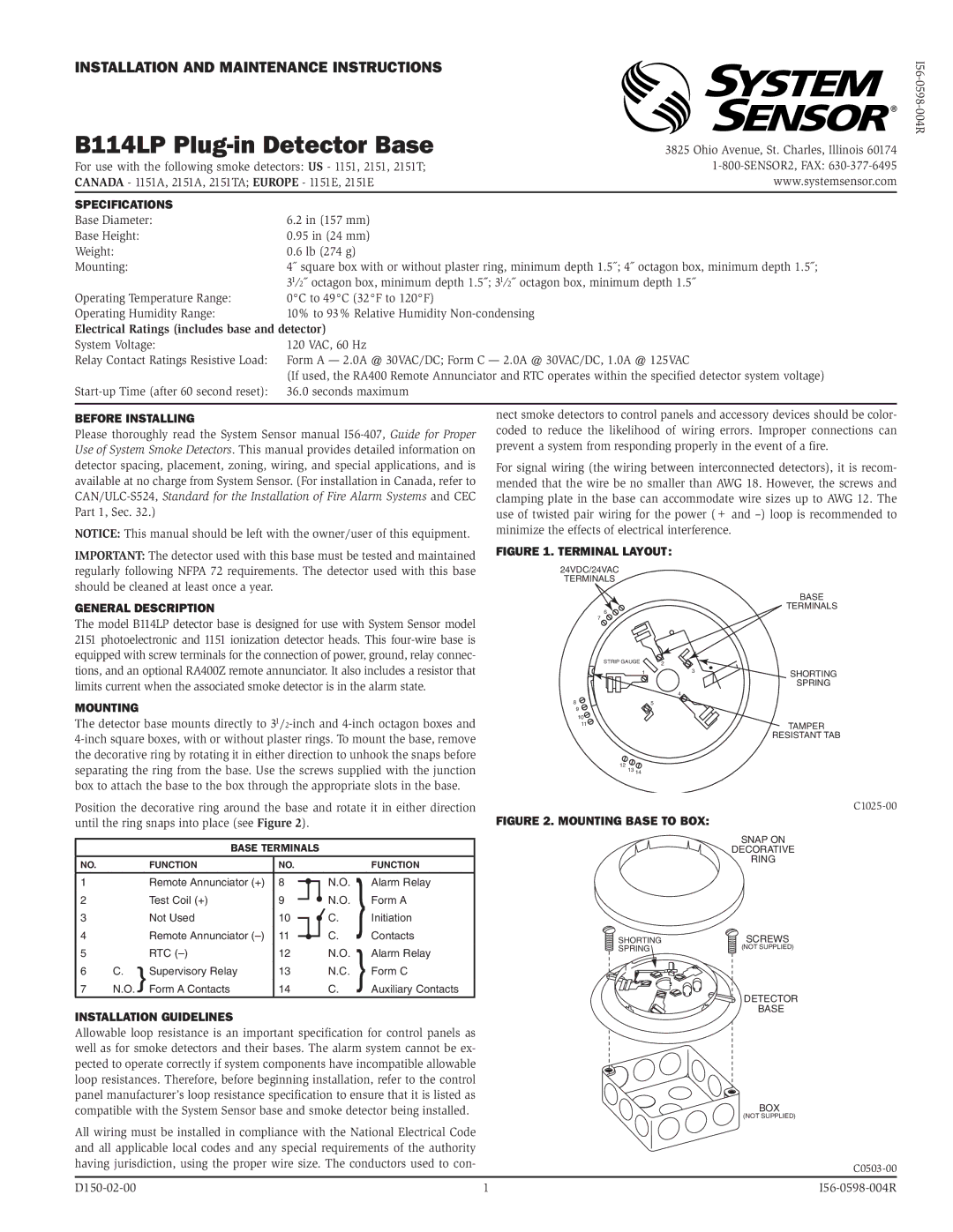
Figure 1. Terminal layout:
24VDC/24VAC
TERMINALS
|
| BASE |
6 |
| TERMINALS |
|
| |
7 |
|
|
STRIP GAUGE | 2 |
|
1 | 3 | SHORTING |
|
| SPRING |
4
85
9
10
11TAMPER RESISTANT TAB
12 13 14
Position the decorative ring around the base and rotate it in either direction until the ring snaps into place (see Figure 2).
BASE TERMINALS
NO. |
| FUNCTION | NO. |
|
|
| FUNCTION | |
1 |
| Remote Annunciator (+) | 8 |
|
|
| N.O. | Alarm Relay |
|
|
|
| |||||
2 |
| Test Coil (+) | 9 |
|
|
| N.O. | Form A |
|
|
|
| |||||
3 |
| Not Used | 10 |
|
|
| C. | Initiation |
|
|
|
| |||||
4 |
| Remote Annunciator | 11 |
|
|
| C. | Contacts |
|
|
|
| |||||
5 |
| RTC | 12 |
|
|
| N.O. | Alarm Relay |
6 | C. | Supervisory Relay | 13 |
|
|
| N.C. | Form C |
7 | N.O. | Form A Contacts | 14 |
|
|
| C. | Auxiliary Contacts |
Installation Guidelines
Figure 2. Mounting base to box:
SHORTING
SPRING ![]()
SNAP ON
DECORATIVE
RING
SCREWS
(NOT SUPPLIED)
DETECTOR
BASE
Allowable loop resistance is an important specification for control panels as well as for smoke detectors and their bases. The alarm system cannot be ex- pected to operate correctly if system components have incompatible allowable loop resistances. Therefore, before beginning installation, refer to the control panel manufacturer’s loop resistance specification to ensure that it is listed as compatible with the System Sensor base and smoke detector being installed.
All wiring must be installed in compliance with the National Electrical Code and all applicable local codes and any special requirements of the authority having jurisdiction, using the proper wire size. The conductors used to con-
BOX
(NOT SUPPLIED)
| 1 |