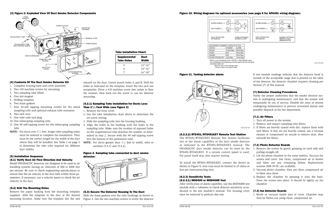
[3] Figure 1: Exploded View Of Duct Smoke Detector Components
Figure 10. Wiring diagrams for optional accessories (see page 6 for APA451 wiring diagram):
DETECTOR BOARD
SAMPLING TUBE
FILTERS
DETECTOR
COVER
COVER MOUNTING
Tube Installation Chart:
Supplemental | Duct |
Tube Holes | Width |
ACCESSORY CURRENT LOADS AT 24 VDC
DEVICE | STANDBY | ALARM |
APA451 | 12.5mA Max. | 30mA Max. |
PA400 | 0mA | 15mA Max. |
RA400Z | 0mA | 10mA Max. |
RTS451/RTS451KEY | 12mA Max. | 7.5mA Max. |
When a unit is powered at the 120VAC or 220/240VAC input,
any combination of accessories may be used such that the givenA78-2354-05accessory loads are:
60mA or less in the standby state, 110mA or less in the alarm state.
[4]Contents Of The Duct Smoke Detector Kit
1. Complete housing base and cover assembly
2. Two #10 machine screws for mounting
3. Two sampling tube filters
4. One test magnet
5. Drilling template
6. Two foam gaskets
7. Four #6-self tapping mounting screws for the metal sampling tube and optional exhaust tube extension
8. Two jack nuts
9. One inlet tube end plug
10. One telescoping sampling tube
11. One #8 self-tapping screw for the telescoping sampling tube
NOTE: For ducts over 11/2 feet, longer inlet sampling tubes must be ordered to complete the installation. They must be the correct length for the width of the duct where they will be installed. See Table 1 on page 3 to determine the inlet tube required for different duct widths.
smooth on the duct. Center punch holes A and B. Drill the holes as indicated on the template. Insert the two jack nut receptacles. Drive a #10 machine screw into jacket to flare the retainer, then back out the screw to use for detector mounting.
[5.2.1] Sampling Tube Installation for Ducts Less Than 11/2 Feet Wide (see Figure 2)
1.Remove the front cover.
2.Use the tube installation chart above to determine the set screw setting.
3.Slide the sampling tube into the housing bushing.
4.Align the holes in the bushing with the holes in the sampling tube. Make sure the number of exposed holes on the supplemental tube matches the number as deter- mined in step 2. Secure with the #8 self-tapping screw
into the bottom of the permanent tube.
NOTE: For ducts greater than 11/2 feet in width, refer to sections [5.4.1] and [5.4.2].
Figure 2. Sampling tube connected to duct smoke
A78-2325-00
[6.2.2.2] RTS451/RTS451KEY Remote Test Station The RTS451/RTS451KEY Remote Test Station facilitates test of the alarm capability of the duct smoke detector as indicated in the RTS451/RTS451KEY manual. The DH100ACDC duct smoke detector can be reset by the RTS451/RTS451KEY. If a system control panel is used,
of the detector, the detector chamber requires cleaning per Section [7] of this manual.
[7] Detector Cleaning Procedures
Notify the proper authorities that the smoke detector sys- tem is undergoing maintenance, and that the system will temporarily be out of service. Disable the zone or system undergoing maintenance to prevent unwanted alarms and possible dispatch of the fire department.
[7.1] Air Filters
1.Turn off power to the system.
2.Remove and inspect sampling tube filters.
3.If filters are heavily coated with dirt, replace them with new filters. If they are not heavily coated, use a vacuum cleaner or compressed air nozzle to remove dust, then reinstall the filters.
[7.2] Photo Detector Boards
1. Remove the screen by gently grasping on each side and |
pulling straight off. |
[5] Installation Sequence
[5.1] Verify Duct Air Flow Direction And Velocity
Model DH100ACDC detectors are designed to be used in air handling systems having air velocities of 500 to 4000 feet per minute. Be sure to check engineering specifications to ensure that the air velocity in the duct falls within these pa- rameters. If necessary, use a velocity meter to check the air velocity in the duct.
[5.2] Drill The Mounting Holes
Remove the paper backing from the mounting template supplied. Affix the template to the duct at the desired mounting location. Make sure the template lies flat and
detector:
[5.3] Secure The Detector Housing To The Duct
Slide the foam gaskets over the tube bushings as shown in Figure 3. Use the two machine screws to screw the detector
the panel itself may also require testing.
To install the RTS451/RTS451KEY, connect the device as shown in Figure 9; wire runs must be limited to 25 ohms or less per interconnecting wire.
[6.2.3] Sensitivity Tests
[6.2.3.1] MOD400 or MOD400R Test
After verification of alarm capability, use the MOD400R test module with a voltmeter to check detector sensitivity as in- dicated in the test module’s manual. The housing cover must be removed to perform this test.
2. | Lift the photo chamber in the same fashion. Vacuum the |
| screen and cover. Use clean, compressed air to loosen |
| and blow out any remaining debris. Replacement |
| screens (S08-39-01) are available. |
3. | Vacuum photo chamber, then use clean compressed air |
| to blow area clean. |
4. | Replace the chamber by pressing it onto the base. |
| Press the screen into place. It should fit tightly on the |
| chamber. |
[7.3] Ion Detector Boards
1.Brush or vacuum inside area of cover. Chamber may then be blown out using clean, compressed air.